
Introduction
Put a smile on your face and replace your upper case.
What you need
-
-
Remove the following 10 screws securing the lower case to the Air:
-
Six 2.8 mm Phillips screws.
-
Two 3.8 mm Phillips screws.
-
Two 5.4 mm Phillips screws.
-
-
-
Slightly lift the lower case near the vents and push it toward the rear of the computer to free the mounting tabs.
-
-
-
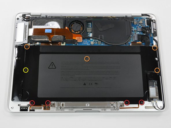
Remove the following nine screws securing the battery to the Air:
-
Four 2.9 mm Phillips.
-
Four 3.8 mm Phillips.
-
One 7.2 mm Phillips.
-
-
-
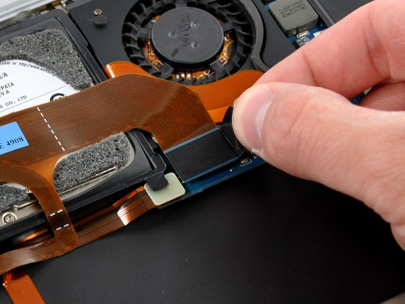
Disconnect the port hatch ribbon cable from the logic board by pulling it straight up by its black pull tab.
-
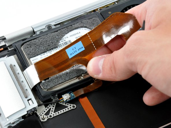
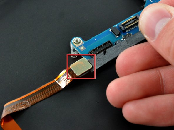
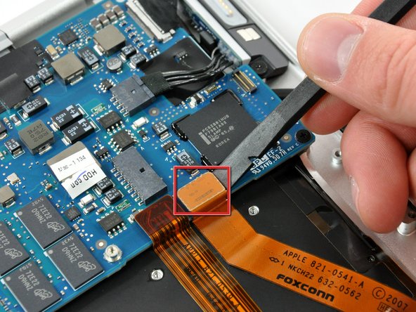
Pull the audio out ribbon cable off the adhesive securing it to the upper case.
-
Use a spudger to pry the audio out ribbon cable connector board off the hard drive bracket.
-
-
-
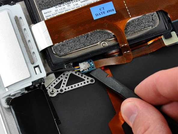
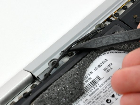
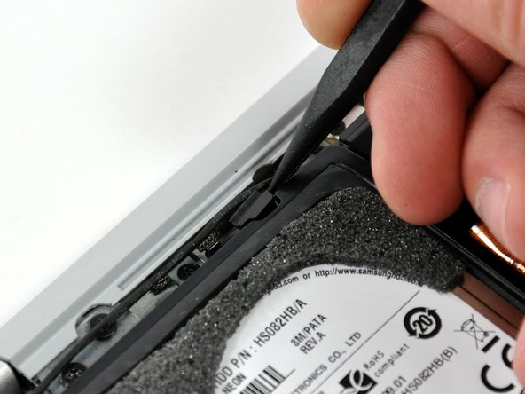
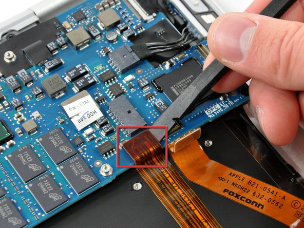
Use the sharp end of a spudger to de-route the microphone cable from the hard drive bracket.
-
Remove the cosmetic screw cover from the adhesive securing it to the hard drive bracket.
-
-
-
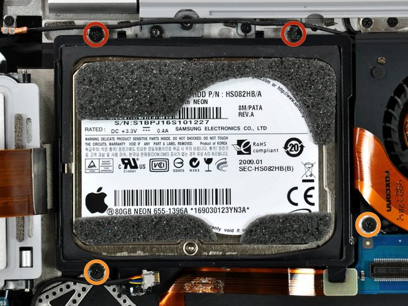
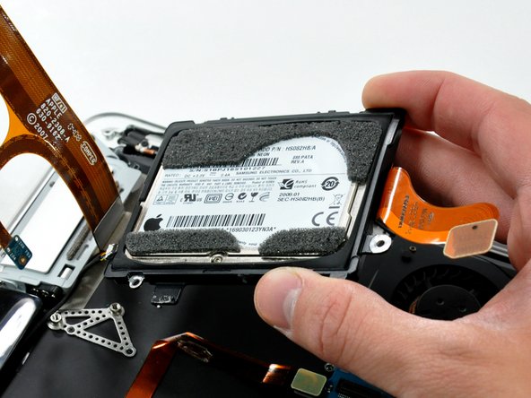
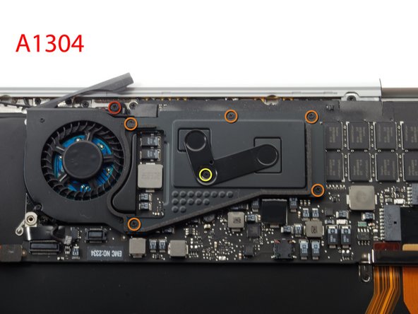
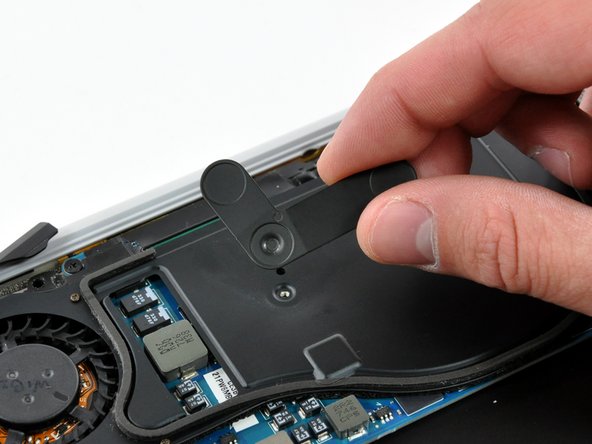
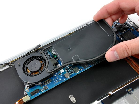
Remove the four Phillips screws securing the hard drive assembly to the upper case:
-
Two 4.7 mm screws.
-
Two 3.9 mm screws.
-
-
-
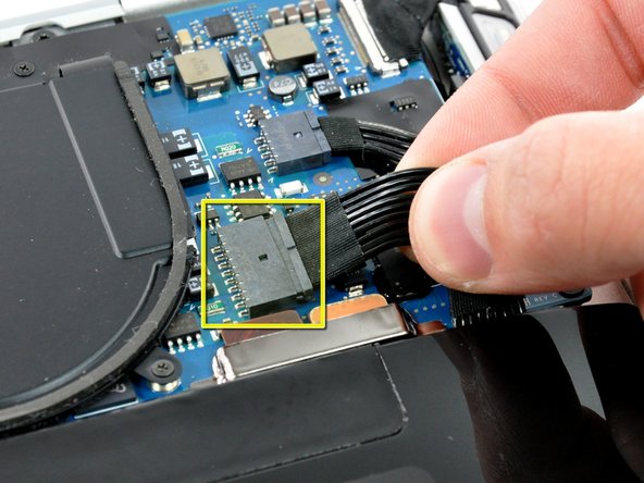
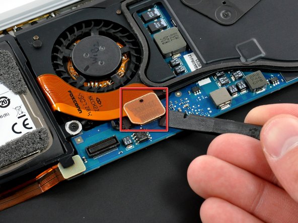
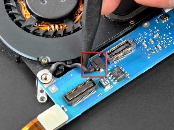
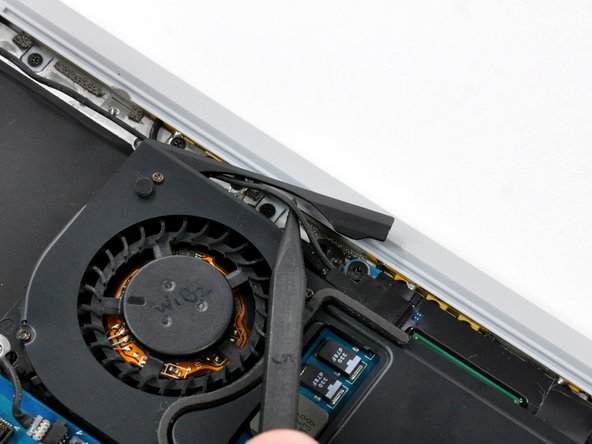
Use the tip of a spudger to pull the fan cable connector straight away from its connector on the logic board.
-
-
-
One 5.9 mm Phillips screw.
-
Two 1.9 mm Phillips screws.
-
One 1.9 mm Phillips screw.
-
One 5.0 mm Phillips screw
-
Five 1.9 mm Philips screws.
-
One 2.5 mm Phillips screw.
-
-
-
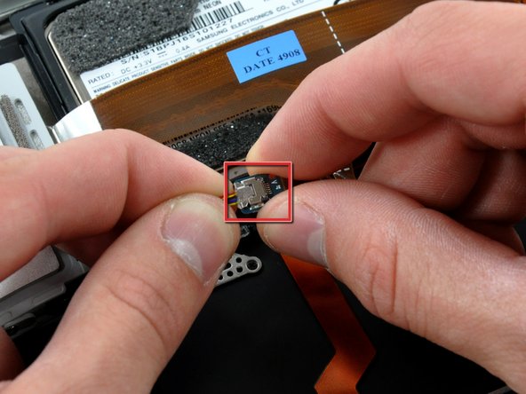
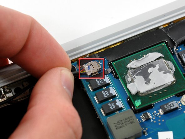
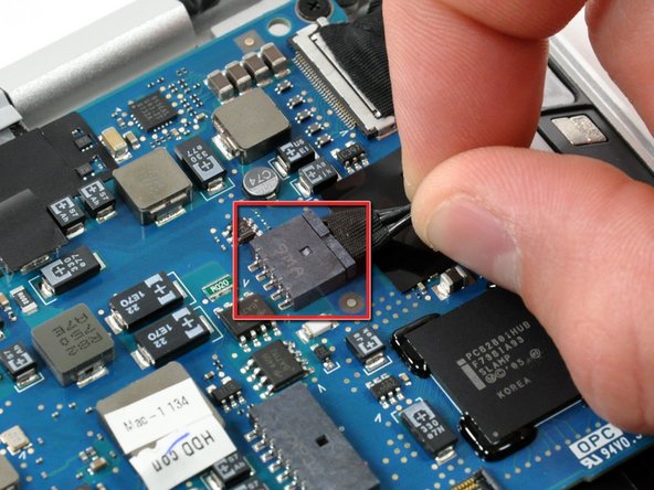
Disconnect the microphone cable by pulling its connector straight away from the socket on the logic board.
-
-
-
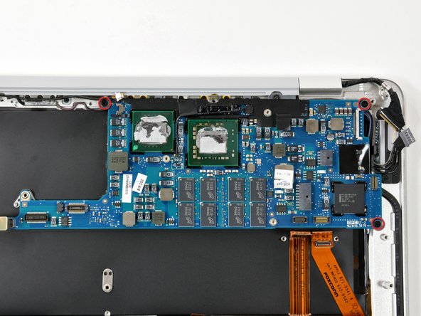
Remove the two small Phillips screws securing the logic board bracket to the upper case.
-
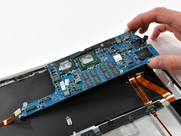
Lift the logic board bracket out of the upper case.
-
-
-
Use a spudger to pry the AirPort/Bluetooth and trackpad control cable connectors up off the logic board.
-
-
-
Disconnect the DC-In cable by pulling its connector straight away from the socket on the logic board.
-
-
-
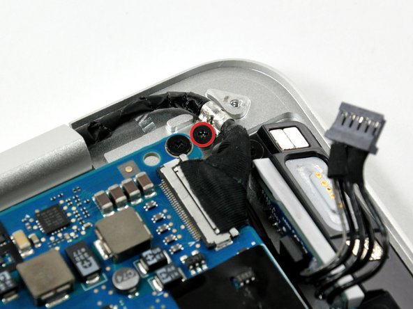
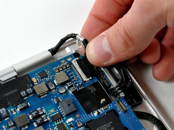
Remove the small Phillips screw securing the display data cable ground loop to the upper case.
-
Disconnect the display data cable by pulling its connector straight away from the socket on the logic board.
-
-
-
Remove the two following screws securing the AirPort/Bluetooth board bracket to the upper case:
-
One 4.7 mm Phillips.
-
One 3.9 mm Phillips.
-
-
-
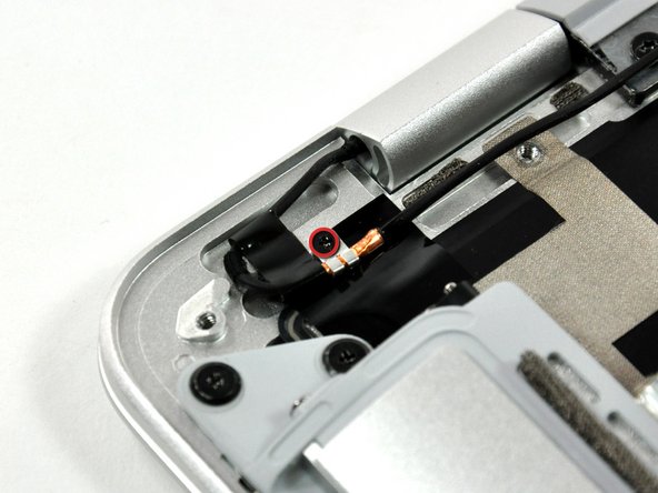
Remove the single Phillips screw securing the microphone cable ground loop to the upper case.
-
-
-
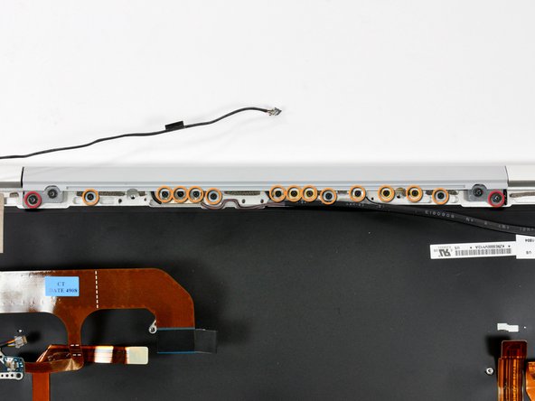
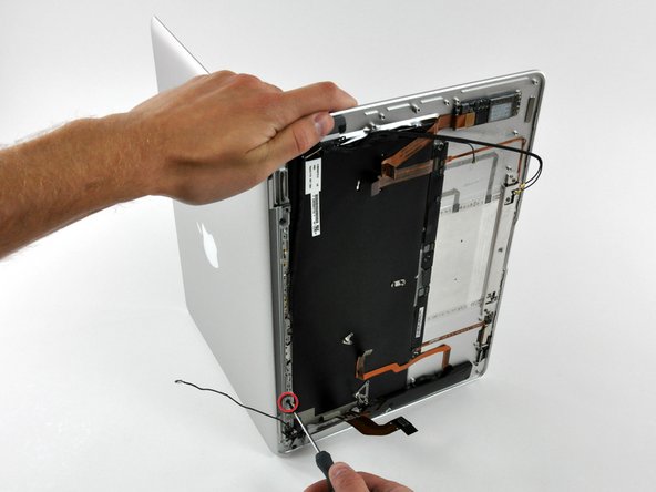
Open the Air so the display is perpendicular to the upper case and place it on a table as shown.
-
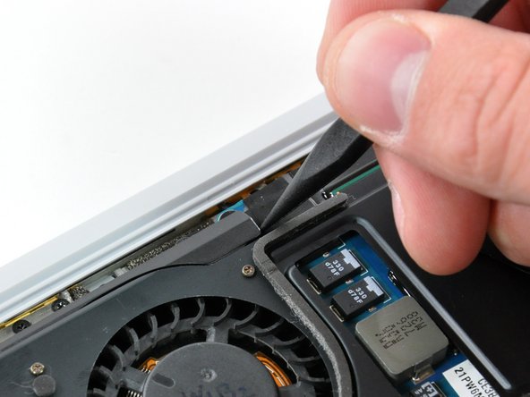
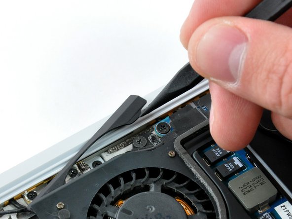
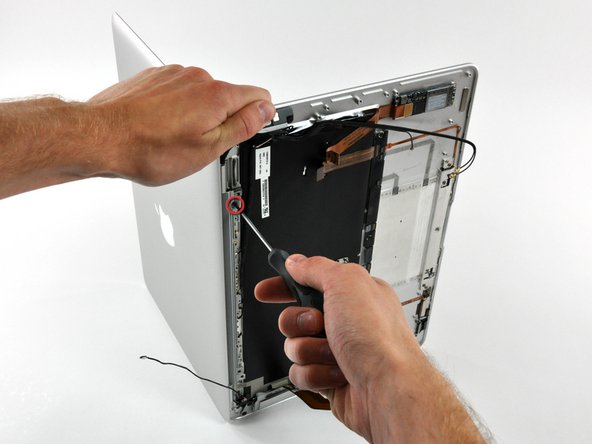
While holding the top of the Air with one hand, remove the T6 Torx screw from the lower display bracket.
-
-
-
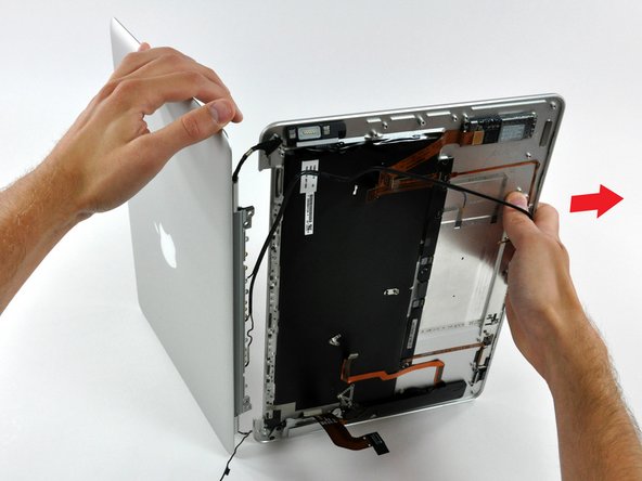
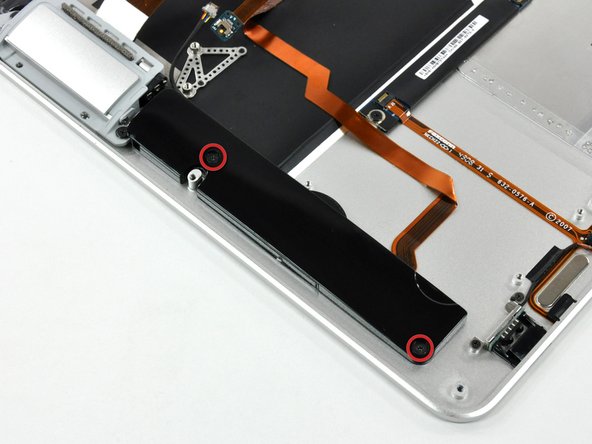
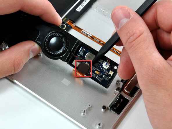
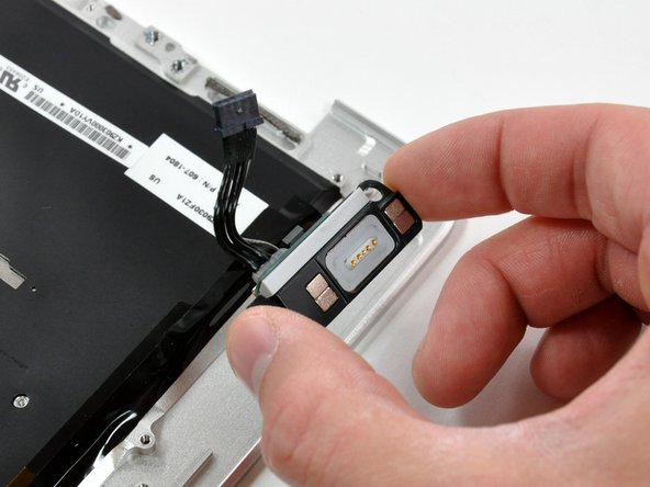
Rotate the speaker assembly toward the center of the Air.
-
Use the pointed end of a spudger to pry the audio cable connector up off the audio board.
-
-
-
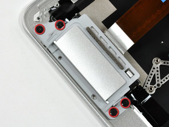
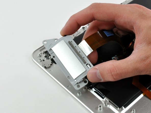
Remove the four partially threaded Phillips screws securing the port hatch assembly to the upper case.
-
Lift the port hatch assembly out of the upper case.
-
-
-
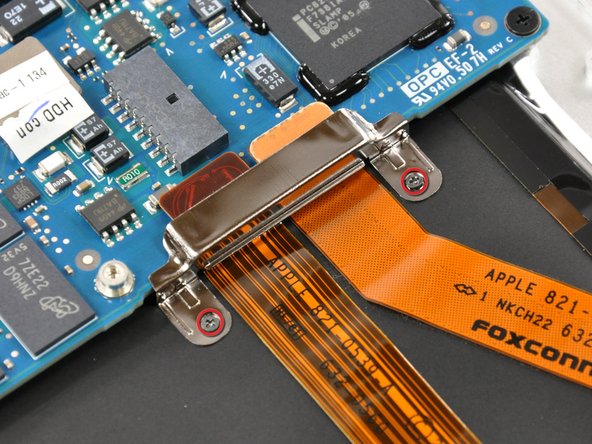
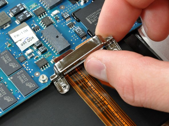
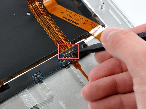
Use the pointed end of a spudger to flip up the retaining flap on the trackpad control cable socket.
-
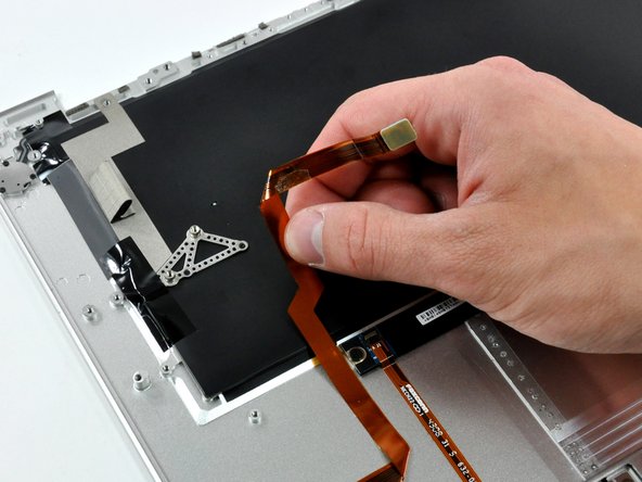
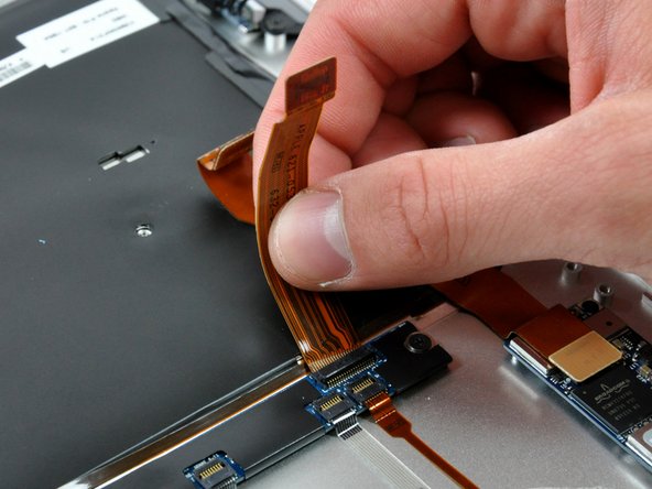
Peel the trackpad control cable off the adhesive securing it to the upper case.
-
Pull the trackpad control cable out of its socket.
-
-
-
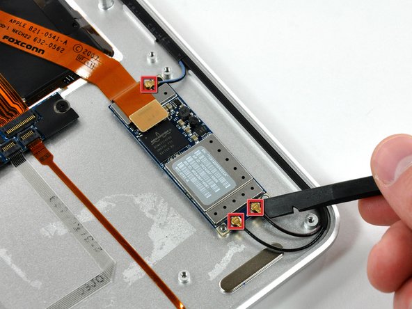
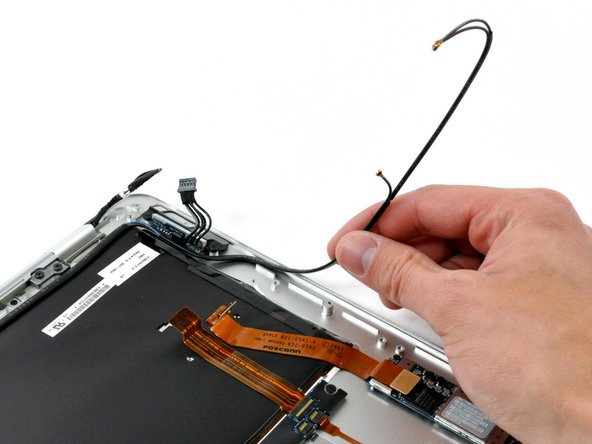
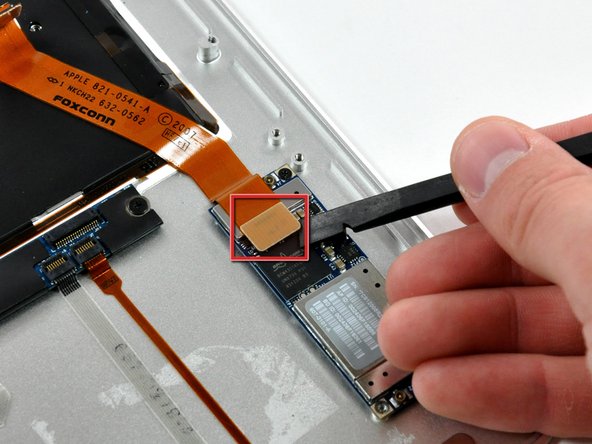
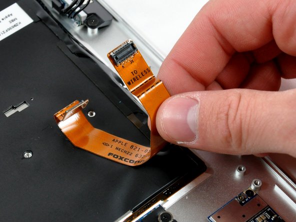
Use a spudger to pry the AirPort/Bluetooth cable connector up off the AirPort/Bluetooth board.
-
Peel the AirPort/Bluetooth cable off the adhesive securing it to the upper case.
-
-
-
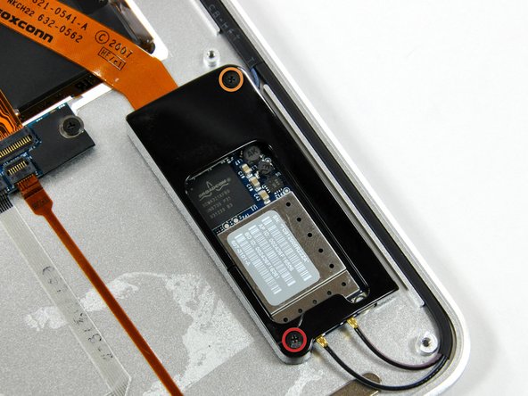
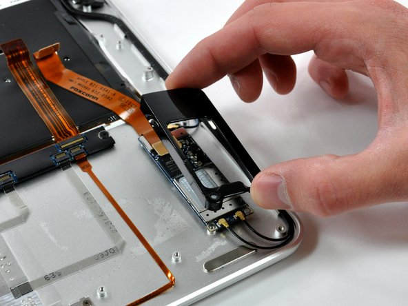
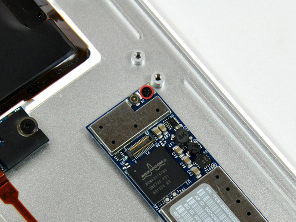
Remove the single Phillips screw securing the AirPort/Bluetooth board to the upper case.
-
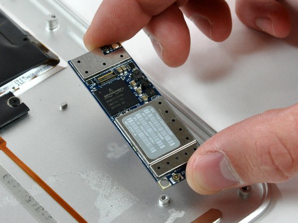
Lift the AirPort/Bluetooth board out of the upper case.
-
-
-
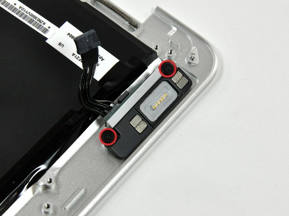
Remove the two Phillips screws securing the DC-In board to the upper case.
-
Lift the DC-In board out of the upper case.
-
Upper case remains.
-


To reassemble your device, follow these instructions in reverse order.
To reassemble your device, follow these instructions in reverse order.
