
Introduction
The time and date, as well as other settings, are kept by the PRAM battery when your machine is off. The PRAM battery on early 2009 MacBooks is non-replaceable.
What you need
-
-
Use a coin to rotate the battery-locking screw 90 degrees clockwise.
-
-
-
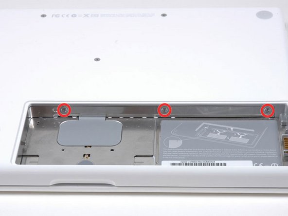
Unscrew the three evenly-spaced Phillips screws from along the rear wall of the battery compartment.
-
-
-
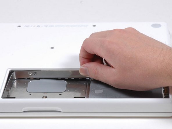
Rotate the L-shaped memory cover so it clears the battery compartment opening and lift it up and out of the computer.
-
-
-
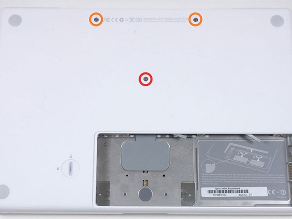
Remove the following 3 screws:
-
One 11 mm Phillips#00 in the middle of the case. (Head: 5mm dia. x .75mm thick)
-
Two 14.5 mm Phillips #00 (Head: 5mm dia. x .75mm thick)
-
-
-
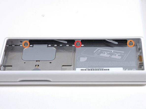
Remove the following 3 screws from the rear wall of the battery compartment:
-
One 3 mm Phillips #0. (Head: 2.75 mm. dia.)
-
Two 4 mm Phillips #0 on the either side. (Head: 2.75mm dia.)
-
-
-
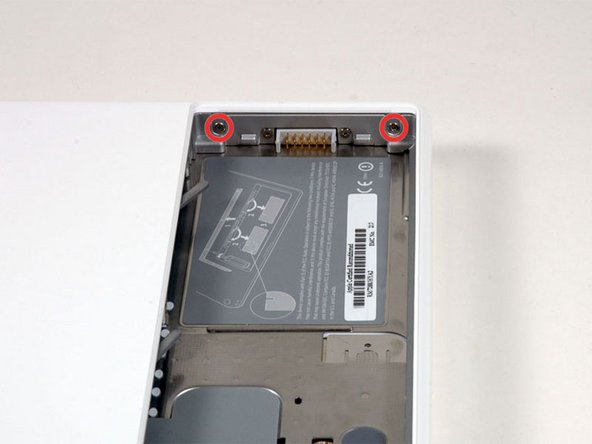
Remove the two Phillips screws from either side of the right wall of the battery compartment (not the ones closest to the battery connector).
-
Two 6.25 mm Phillips #000. (Head: 4 mm. dia. x .5mm thick)
-
-
-
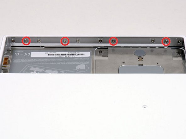
Remove the four indicated Phillips screws from the front wall of the battery compartment. When working from the left, remove the 2nd, 4th, 7th and 9th screw.
-
Four 3.25 mm Phillips #000. (Head: 4 mm. dia. x 4mm thick)
-
-
-
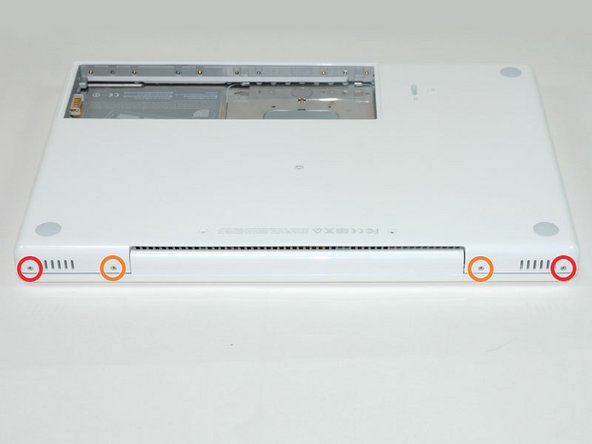
Remove the following 4 screws from the back of the computer:
-
The longer screws go on the inside, shorter screws on the outside.
-
Two 11 mm Phillips #00, with Shank (2.2mm dia. x 2 mm len.) (Head: 3.2 mm. dia. x .5mm thick)
-
Two 7.25 mm Phillips #00, with Shank (2mm dia. x 3.75 mm len.) (Head: 3.2 mm. dia. x .5mm thick)
-
-
-
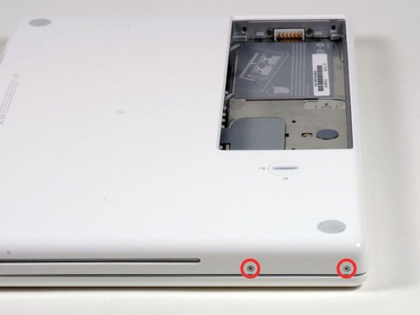
Remove the two Phillips screws from the optical drive side of the computer.
-
Two 5.2 mm Phillips #00, with Shank (2.3mm dia. x 3.5 mm len.) (Head: 3.2 mm. dia. x .5mm thick)
-
-
-
Starting near the display and working around to the front of the computer, pry up on the upper case. A or a medium hard guitar pick may help you to do this.
-
-
-
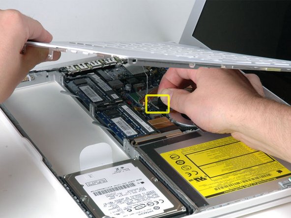
While holding up the upper case, pull up the black tab of the silver cable away from its connector.
-
While you have the upper case removed, you may want to take the opportunity to remove dust, hair, etc. It's best to use a can of compressed air, though if you use a brush, make sure that its bristles are made of a material (usually animal hair) that doesn't generate static electricity, which can destroy electronics.
-
-
-
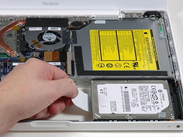
Grasp the white plastic tab attached to the hard drive and pull it to the left, removing the hard drive from the computer.
-
-
-
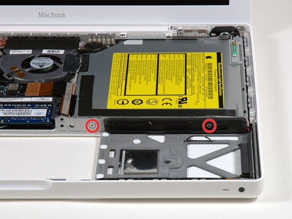
Remove the two Phillips screws from the front edge of the optical drive.
-
Two 3.25 mm Phillips #000, (Head: 4 mm. dia. x .3 mm thick)
-
-
-
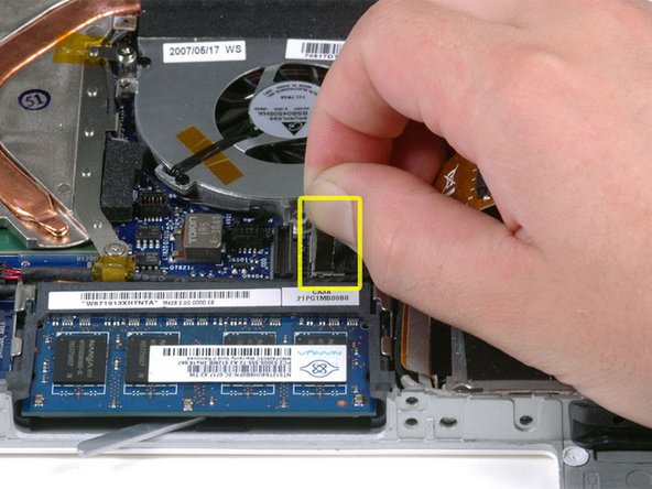
Disconnect the orange optical drive ribbon cable from the logic board. This cable can also be disconnected by prying straight up using a spudger.
-
-
-
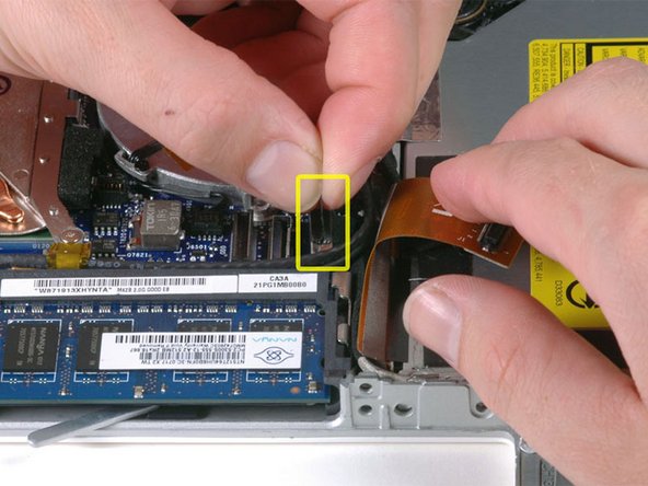
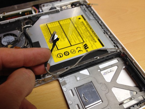
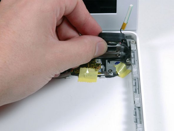
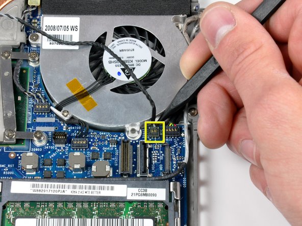
Disconnect the newly revealed display data cable. If there is no pull-tab on the top of the connector, it may be helpful to use a spudger to disconnect this connector.
-
-
-
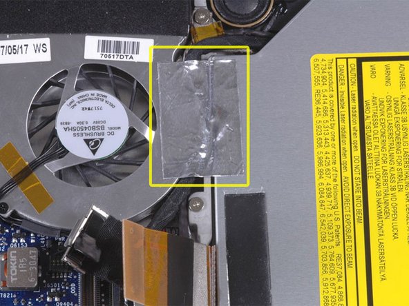
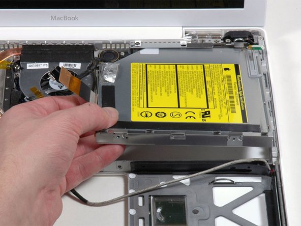
Peel up the foil tape between the fan and the optical drive. Lift the foil tape from the fan side, leaving it attached to the optical drive.
-
During reassembly, be sure to route the cables beneath the tape before reattaching it.
-
-
-
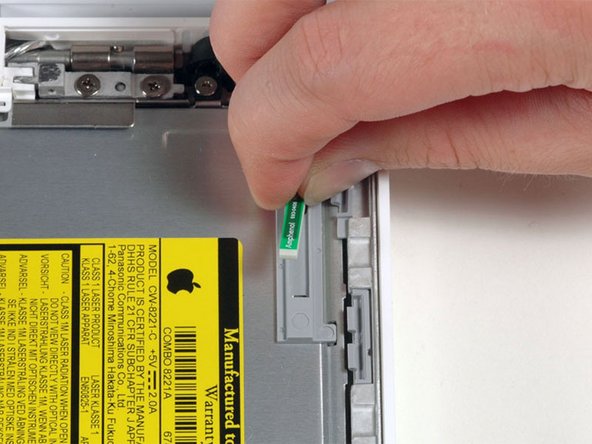
Pull up the display data cable from along the edge of the optical drive to reveal a silver Phillips screw.
-
-
-
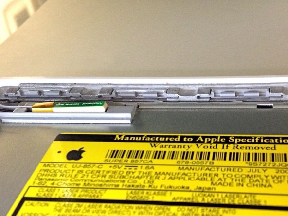
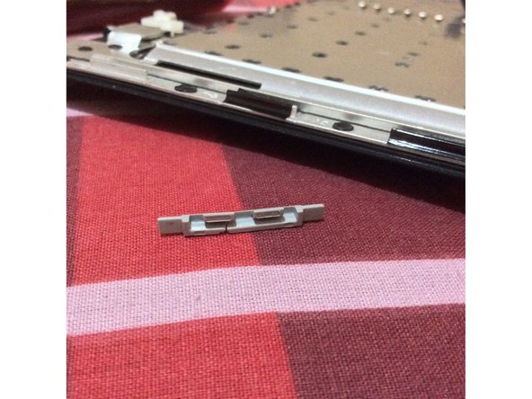
Remove the 2 mm Phillips #00 screw securing the optical drive.
-
The Bluetooth cable may be covering the screw. If so, carefully push it aside. You may need to unscrew the cable clip to free the cable enough.
-
-
-
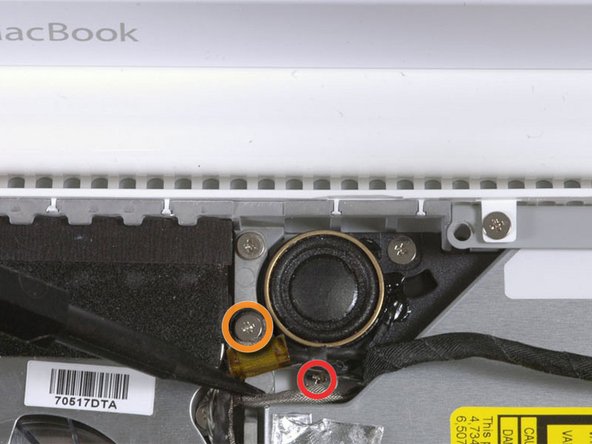
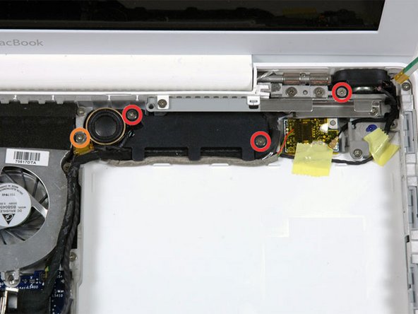
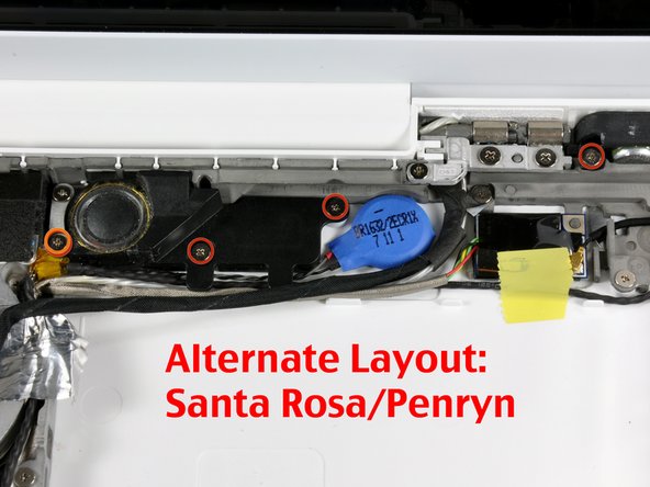
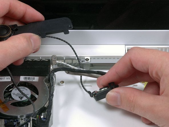
Remove the following 4 Phillips screws:
-
Three 3 mm Phillips securing the subwoofer and right speaker to the lower case.
-
One 7.5 mm Phillips securing the loop in the display data cable to the lower case.
-
-
-
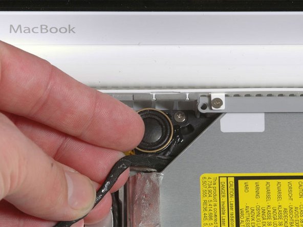
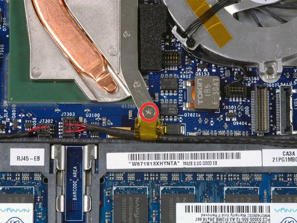
Remove the single Phillips screw securing the ground loop in the right speaker cable to the heat sink.
-
-
-
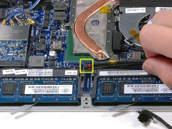
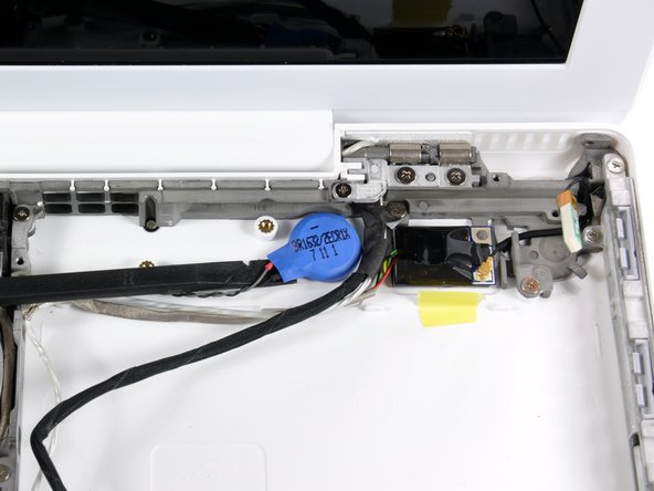
Use a spudger to remove the PRAM battery up from its location on the lower case.
-
Disconnect the PRAM battery cable from the logic board and remove the PRAM battery from the computer.
-


To reassemble your device, follow these instructions in reverse order.
To reassemble your device, follow these instructions in reverse order.
