
Introduction
Use this guide to replace your bare logic board. This requires removal of every component attached to the logic board.
What you need
-
-
Remove the following ten screws securing the lower case to the upper case:
-
Three 13.5 mm (14.1 mm) Phillips screws.
-
Seven 3 mm Phillips screws.
-
-
-
Using both hands, lift the lower case near the vent to pop it off two clips securing it to the upper case.
-
Remove the lower case and set it aside.
-
-
-
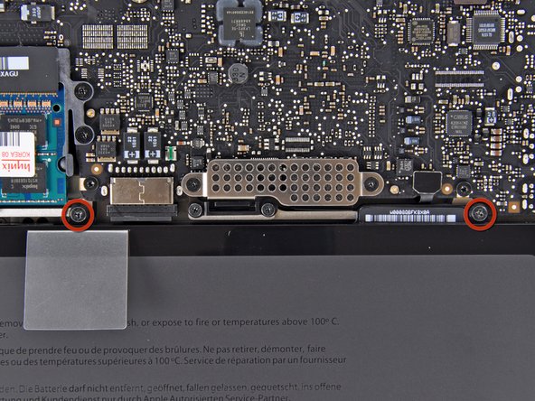
Remove the two 7.4 mm Y1 Tri-Wing screws securing the battery to the upper case.
-
Note: For certain repairs (e.g. hard drive), removing the battery is not necessary but it prevents any accidental shorting of electronics on the motherboard. If you do not remove the battery, please be careful as parts of the motherboard might be electrified.
-
-
-
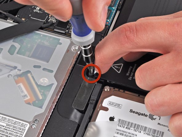
Use the tip of your finger to carefully peel back the corner of the warning label to reveal a hidden Tri-Wing screw.
-
Remove the last 7.4 mm Y1 Tri-Wing screw securing the battery to the upper case.
-
-
-
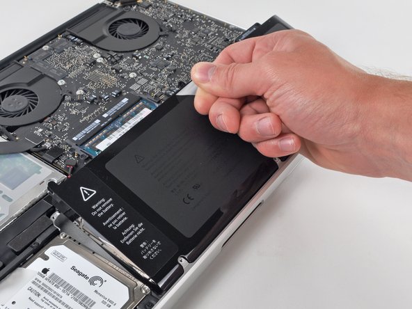
Lift the battery by its plastic pull tab and slide it away from the long edge of the upper case.
-
-
-
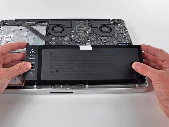
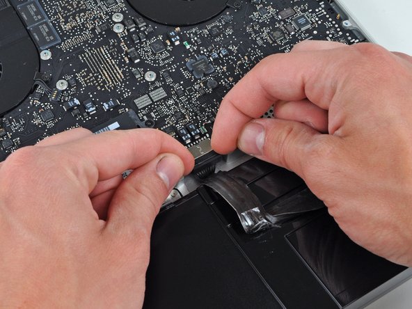
Tilt the battery away from the logic board enough to access the battery cable connector.
-
Pull the battery cable connector away from its socket on the logic board and remove the battery from the upper case.
-
-
-
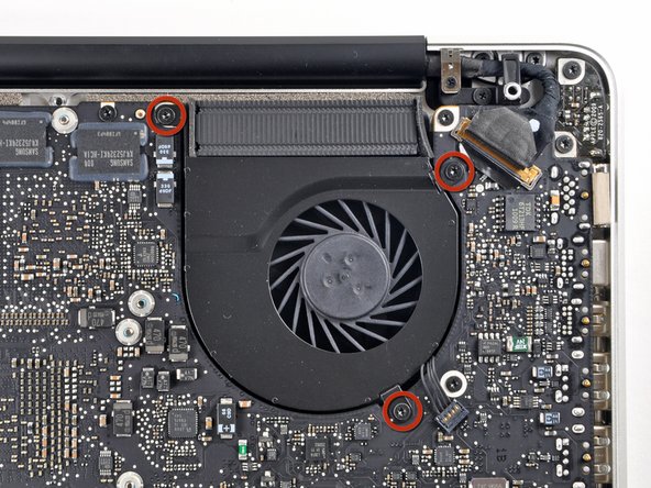
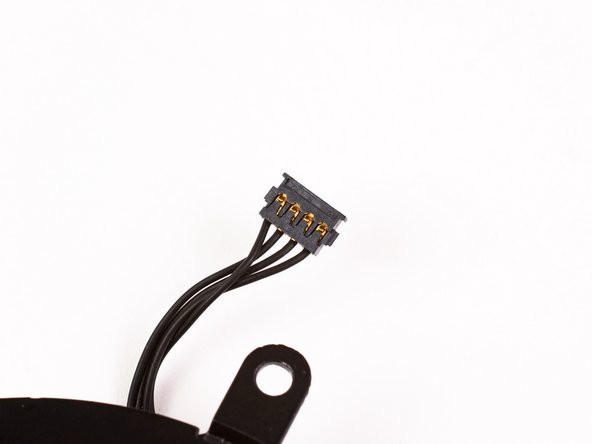
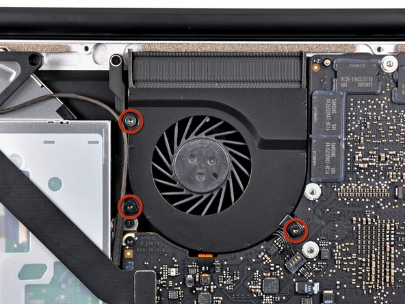
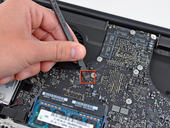
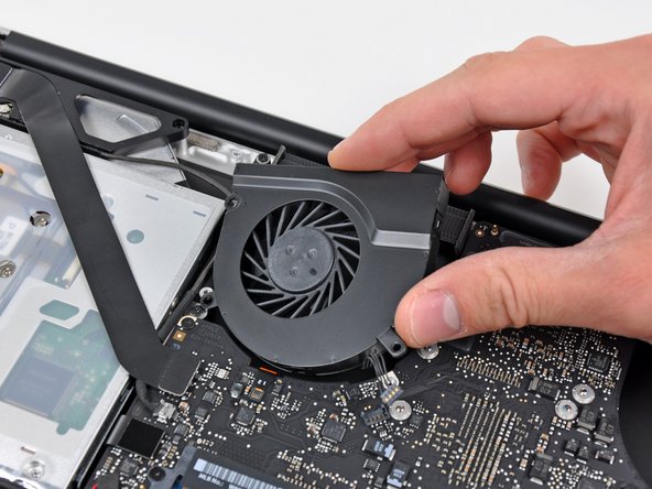
Use the flat end of a spudger to pry the right fan connector up out of its socket on the logic board.
-
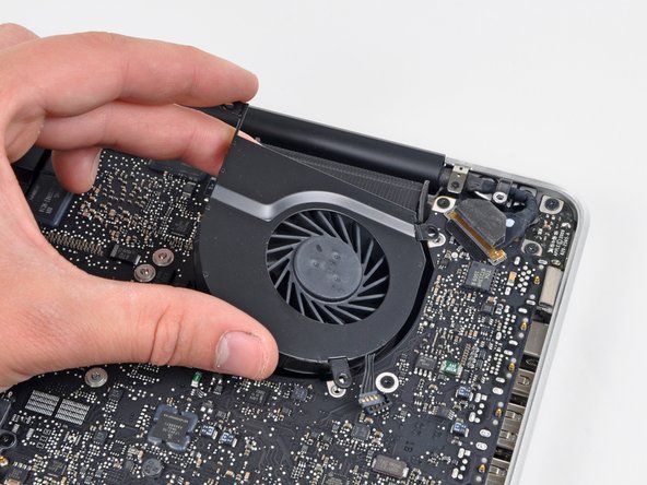
Remove the right fan from the upper case.
-
-
-
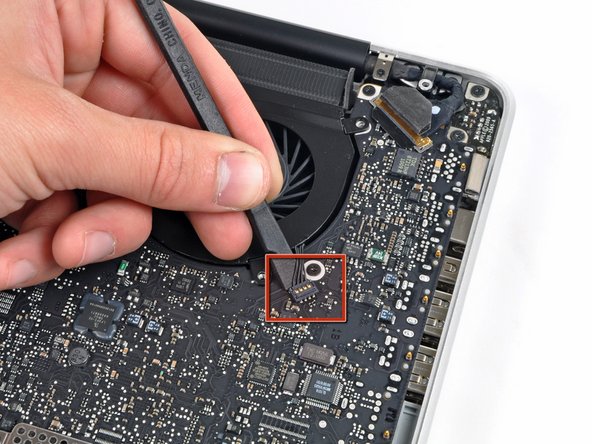
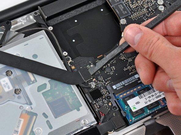
Use the flat end of a spudger to pry the AirPort / Bluetooth ribbon cable up off its socket on the logic board.
-
-
-
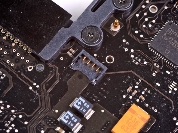
Use the flat end of a spudger to pry the optical drive cable connector up from the logic board.
-
-
-
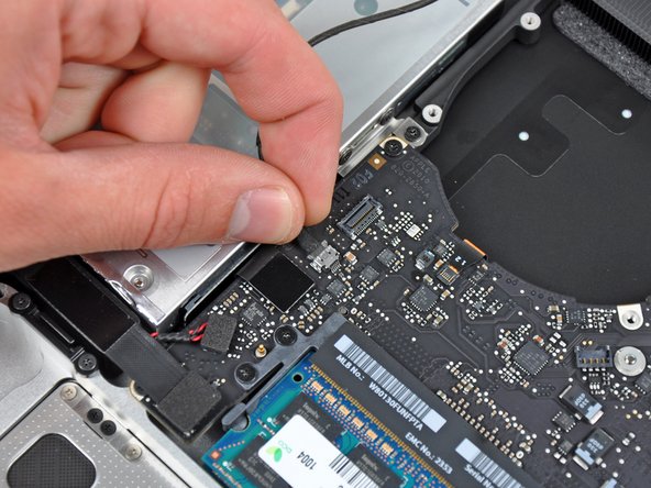
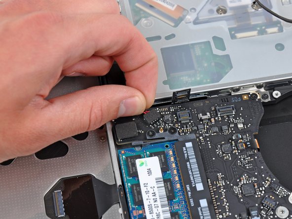
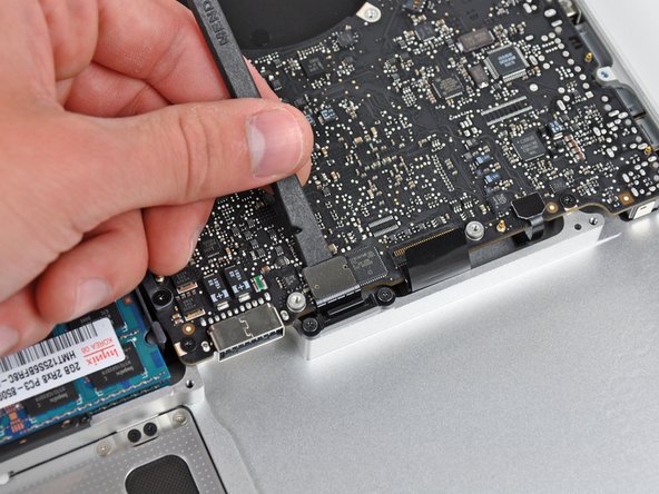
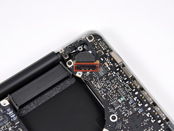
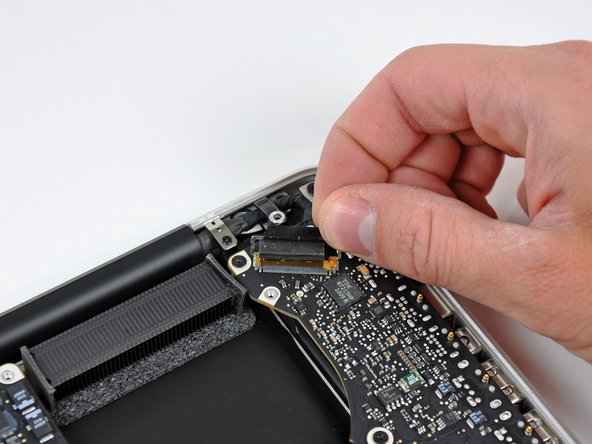
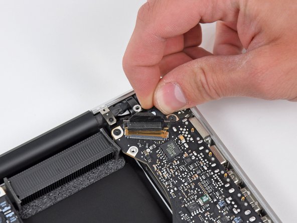
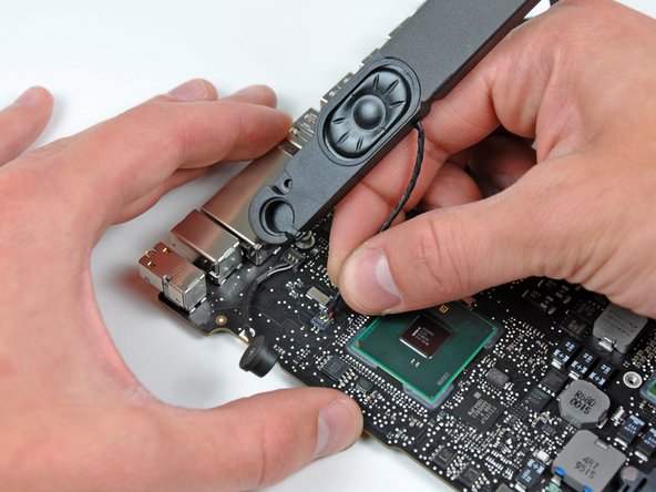
Carefully pull the subwoofer/right speaker cable up to lift its connector out of its socket on the logic board.
-
-
-
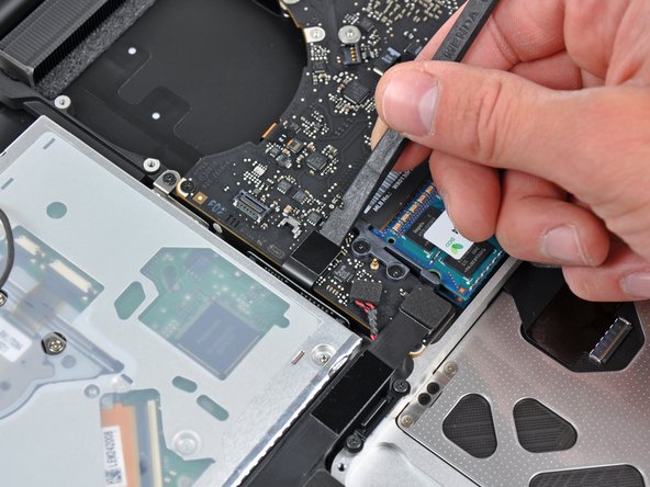
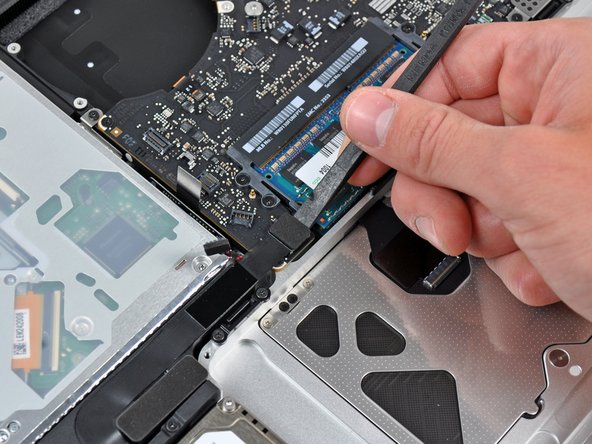
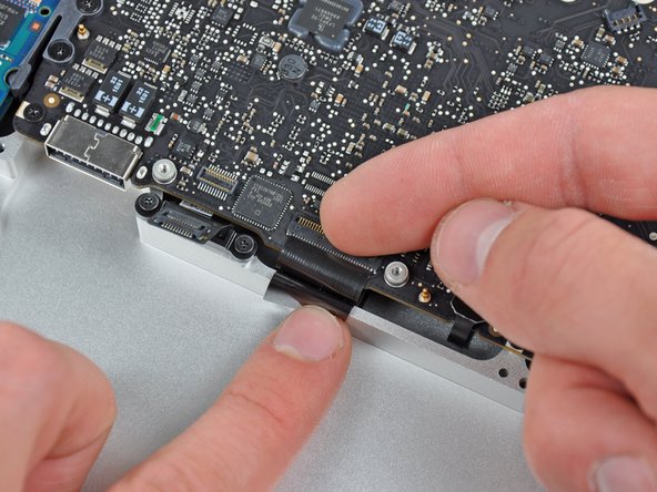
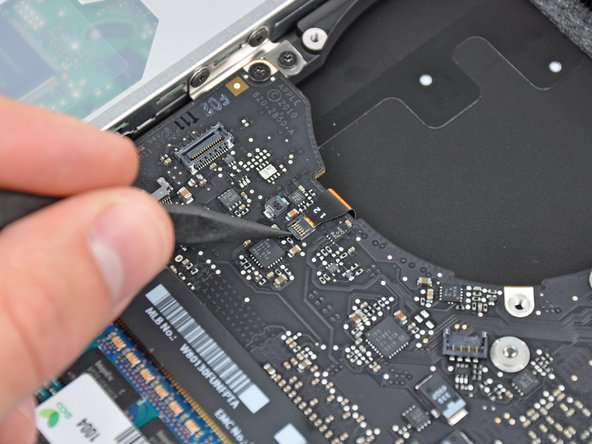
Use the flat end of a spudger to pry the hard drive cable connector up out of its socket on the logic board.
-
-
-
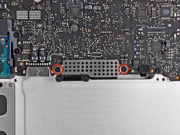
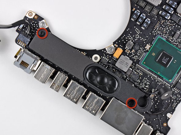
Remove the two short Phillips screws securing the small EMI shield to the logic board.
-
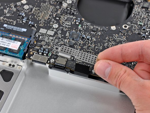
Remove the EMI shield from the logic board.
-
-
-
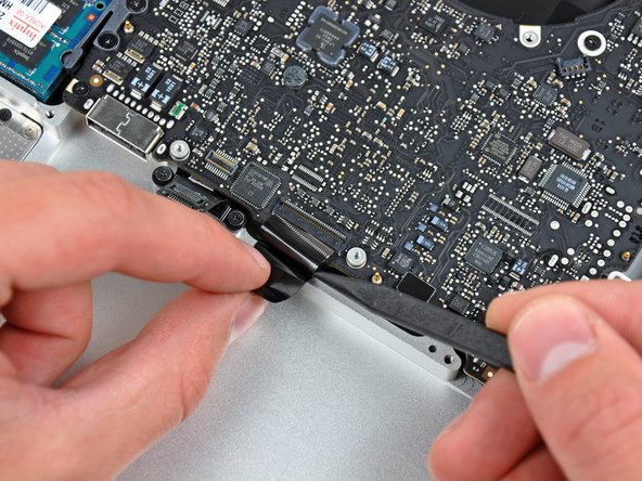
Use the flat end of a spudger to pry the trackpad cable connector up out of its socket on the logic board.
-
-
-
Use your fingernail to carefully flip up the keyboard ribbon cable retaining flap.
-
Use the tip of a spudger to pull the keyboard ribbon cable straight out of its socket.
-
-
-
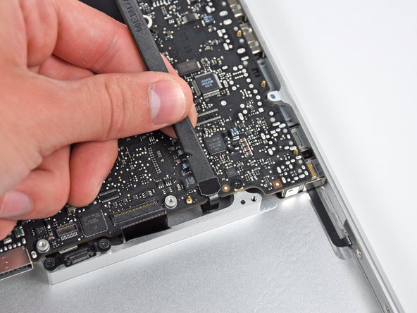
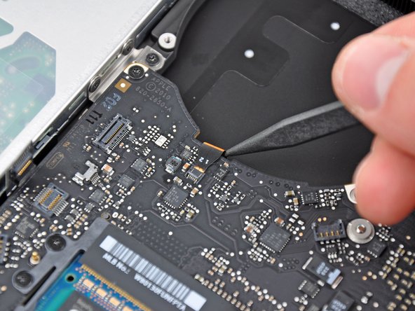
Use the flat end of a spudger to pry the battery indicator cable connector up out of its socket on the logic board.
-
-
-
Grab the plastic pull tab secured to the display data cable lock and rotate it toward the DC-In side of the computer.
-
Pull the display data cable straight out of its socket.
-
-
-
Use the tip of a spudger or your fingernail to flip up the retaining flap on the keyboard backlight ribbon cable socket.
-
Pull the keyboard ribbon cable straight out of its socket.
-
-
-
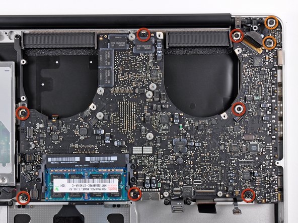
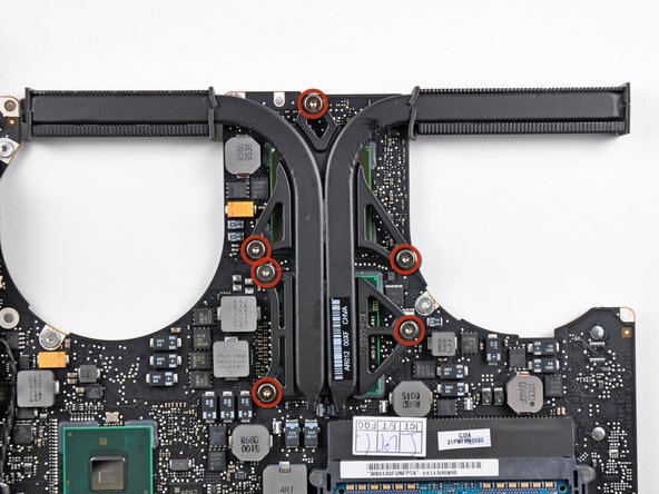
Remove the following screws:
-
Seven 3.3 mm T6 Torx screws securing the logic board to the upper case.
-
Two 8 mm T6 Torx screws securing the DC-In board to the upper case.
-
-
-
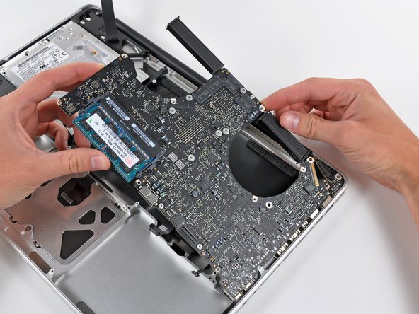
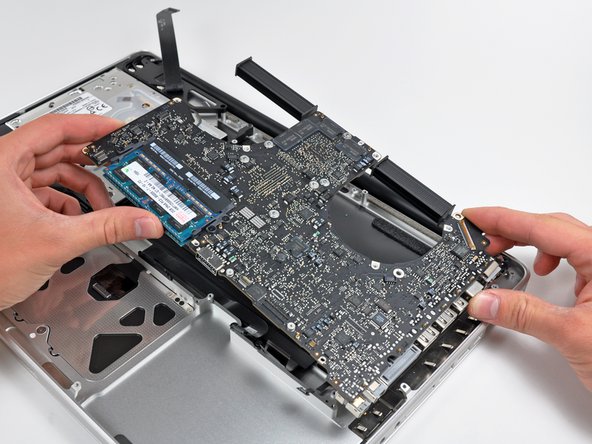
Carefully lift the logic board assembly from the left side and work it out of the upper case, minding the port side that may get caught during removal.
-
-
-
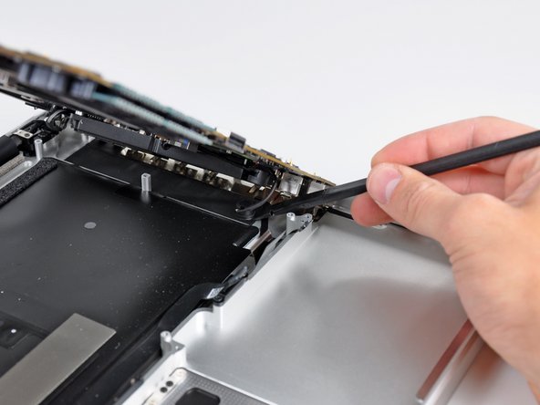
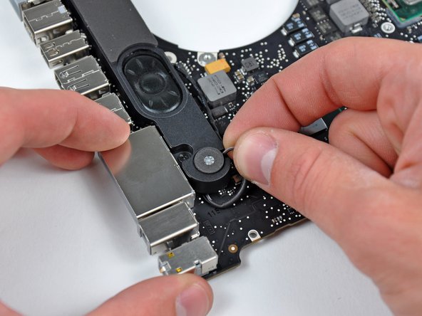
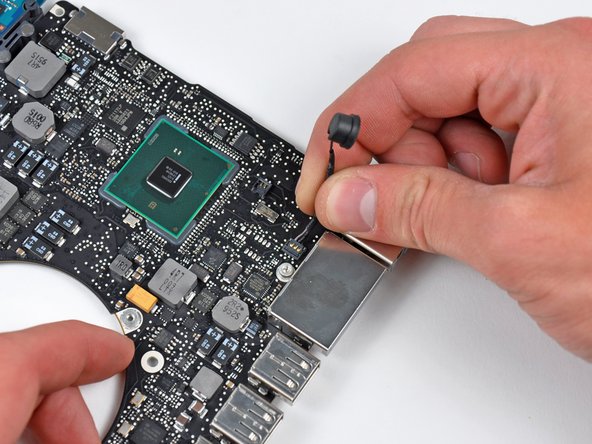
Lift the logic board enough to gain clearance and use a spudger to pry the microphone up off the upper case.
-
-
-
Slide the logic board away from the port openings and lift the assembly out of the upper case.
-
-
-
Carefully pull the left speaker wires upward to lift the left speaker connector out of its socket on the logic board.
-
-
-
Carefully pull the microphone cables upward to lift the microphone connector out of its socket on the logic board.
-
-
-
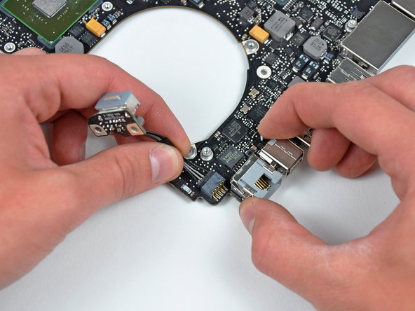
Pull the DC-In board cables toward the heat sink to disconnect the DC-In board from its socket on the logic board.
-
-
-
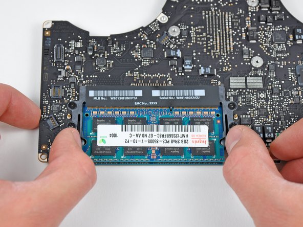
Release the tabs on each side of the RAM chip by simultaneously pushing each tab away from the RAM.
-
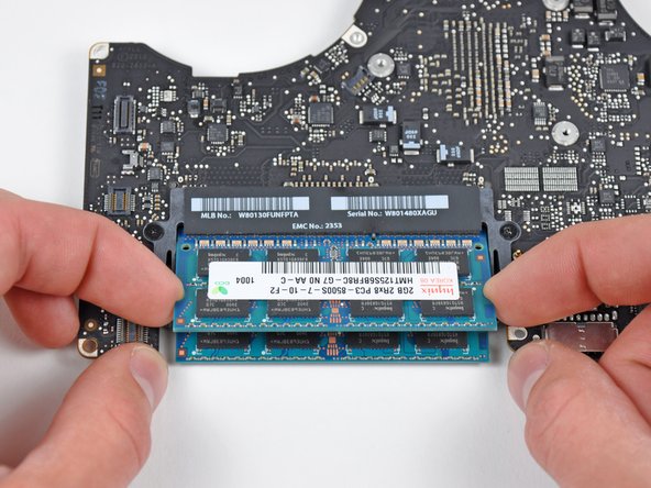
After the RAM chip has popped up, pull it straight out of its socket.
-
Logic board remains.
-
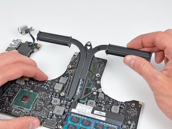
If you need to mount the heat sink back onto the logic board, we have a thermal paste guide that makes replacing the thermal compound easy.
-


To reassemble your device, follow these instructions in reverse order.
To reassemble your device, follow these instructions in reverse order.
