
Introduction
Use this guide to replace the short optical drive ribbon cable connecting the optical drive to the logic board.
What you need
-
-
Remove the following ten screws securing the lower case to the upper case:
-
Three 13.5 mm (14.1 mm) Phillips screws.
-
Seven 3 mm Phillips screws.
-
-
-
Using both hands, lift the lower case near the vent to pop it off two clips securing it to the upper case.
-
Remove the lower case and set it aside.
-
-
-
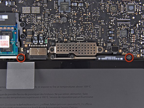
Remove the two 7.4 mm Y1 Tri-Wing screws securing the battery to the upper case.
-
Note: For certain repairs (e.g. hard drive), removing the battery is not necessary but it prevents any accidental shorting of electronics on the motherboard. If you do not remove the battery, please be careful as parts of the motherboard might be electrified.
-
-
-
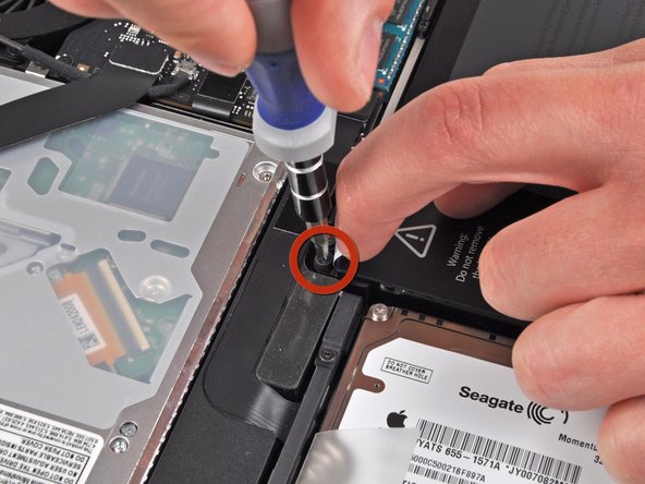
Use the tip of your finger to carefully peel back the corner of the warning label to reveal a hidden Tri-Wing screw.
-
Remove the last 7.4 mm Y1 Tri-Wing screw securing the battery to the upper case.
-
-
-
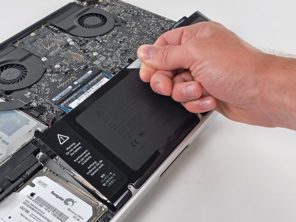
Lift the battery by its plastic pull tab and slide it away from the long edge of the upper case.
-
-
-
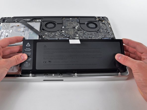
Tilt the battery away from the logic board enough to access the battery cable connector.
-
Pull the battery cable connector away from its socket on the logic board and remove the battery from the upper case.
-
-
-
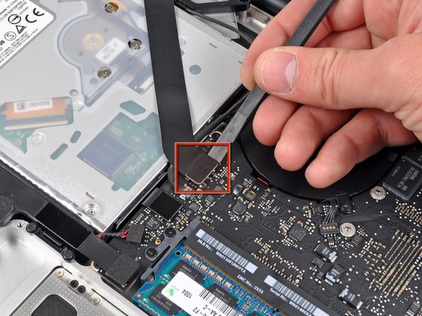
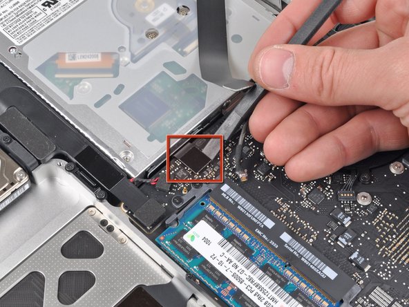
Use the flat end of a spudger to pry the AirPort/Bluetooth ribbon cable connector up off the logic board.
-
-
-
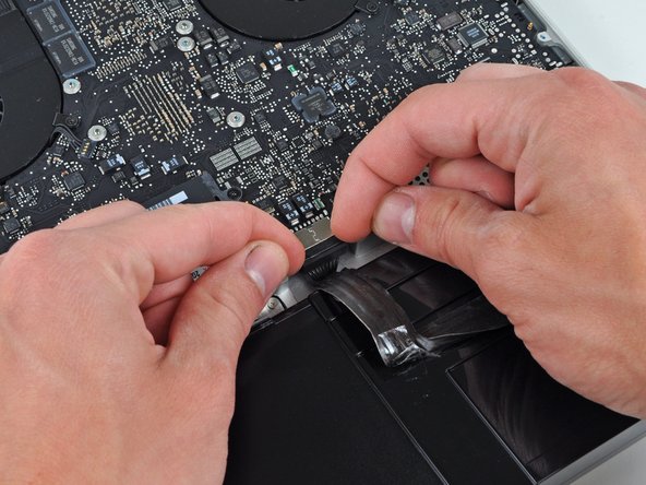
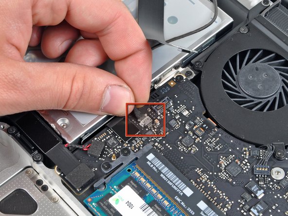
Disconnect the camera cable by pulling its connector away from the socket (toward the optical drive) on the logic board.
-
-
-
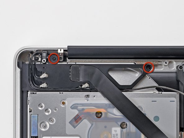
Remove the two Phillips screws securing the AirPort/Bluetooth board housing.
-
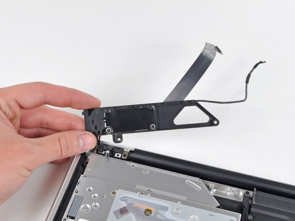
Carefully rotate the AirPort/Bluetooth board housing (with AirPort/Antenna cables still attached) out of the lower case.
-
-
-
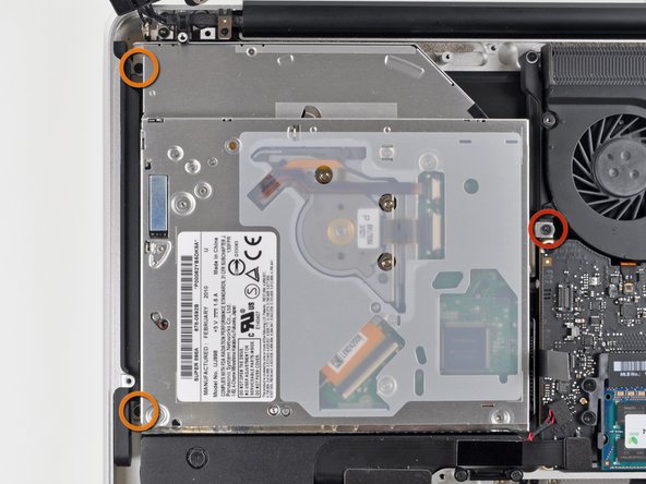
Remove the following three Phillips screws securing the optical drive to the upper case:
-
One 4.5 mm Phillips screw securing the optical drive bracket to the upper case near the fan.
-
Two 2.5 mm Phillips screws securing the optical drive to the upper case near the optical drive opening.
-
-
-
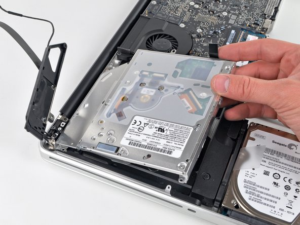
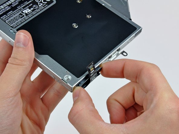
Lift the optical drive near its connector and pull it away from the upper case to remove it from the computer.
-


To reassemble your device, follow these instructions in reverse order.
To reassemble your device, follow these instructions in reverse order.
