
Introduction
This motherboard includes all ports on the right side.
What you need
-
-
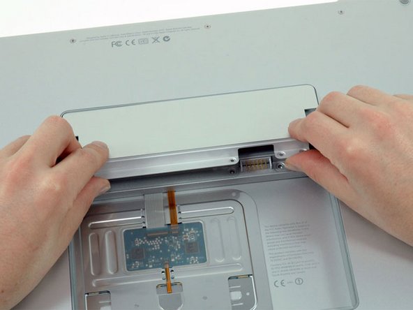
Use your fingers to push both battery release tabs away from the battery and lift the battery out of the computer.
-
-
-
Remove the four identical Phillips 3.4 mm screws from the memory door. These screws have 4 mm diameter heads rather than the 3 mm heads on the body screws.
-
-
-
Lift the memory door up enough to get a grip on it, and slide it toward you, pulling it away from the casing.
-
-
-
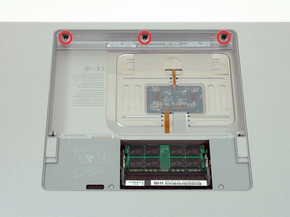
Remove the three Phillips screws in the battery compartment near the latch. Apple was nice enough to tilt these screws at a slight angle to make them easier to remove. On the A1261 these screws have 4 mm diameter heads rather than the 3 mm heads on the body screws.
-
-
-
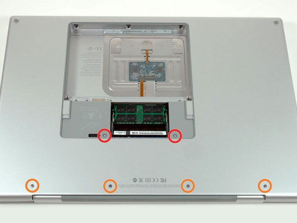
Remove the following six screws:
-
Two 14.5 mm T6 Torx screws on either side of the RAM slot.
-
Four 3.4 mm Phillips screws along the hinge.
-
-
-
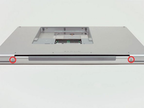
Rotate the computer 90 degrees and remove the two Phillips screws from the rear of the computer.
-
-
-
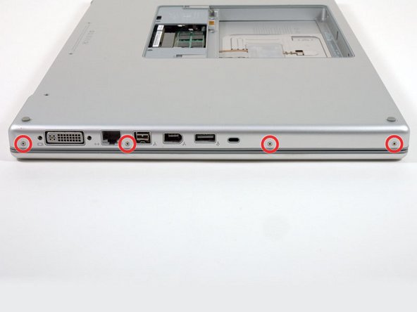
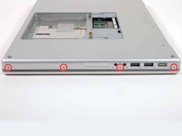
Rotate the computer 90 degrees again and remove the four Phillips screws from the side of the computer.
-
-
-
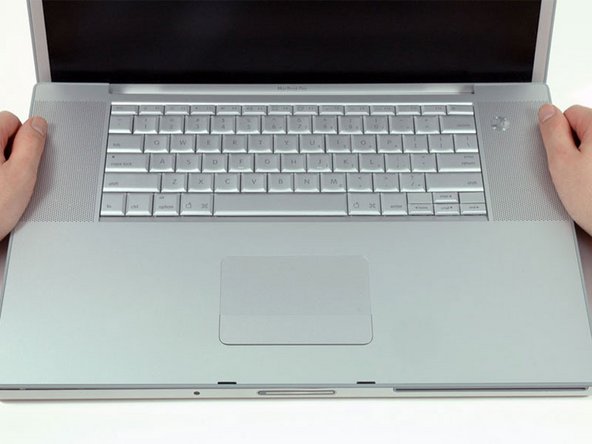
Lift up the back of the case and work your fingers along the sides, freeing the case as you go. Once you have freed the sides, you may need to rock the case up and down to free the front of the upper case.
-
-
-
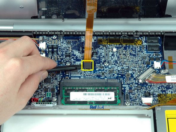
Disconnect the trackpad and keyboard ribbon cable from the logic board.
-
Remove the upper case.
-
-
-
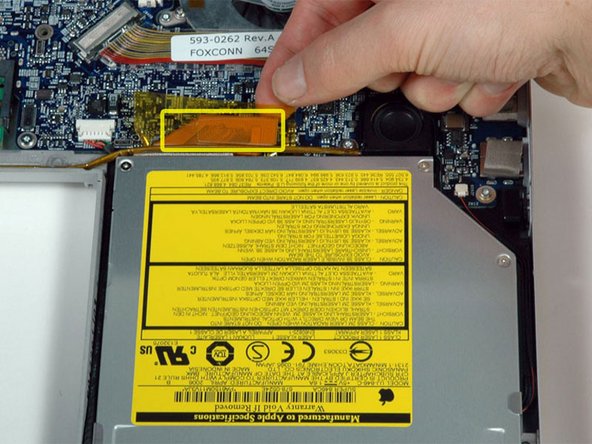
Disconnect the orange SuperDrive ribbon cable from the logic board, removing tape as necessary.
-
-
-
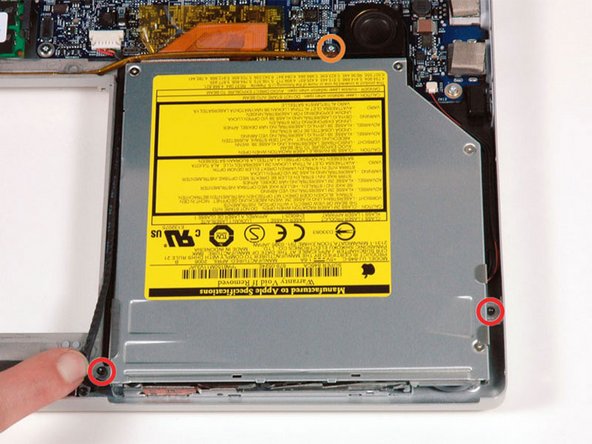
Remove the following three screws:
-
Two black 4 mm T6 Torx screws on either side of the SuperDrive.
-
One 8.7 mm silver (black in some models) T6 Torx screw at the back of the drive near the speaker.
-
-
-
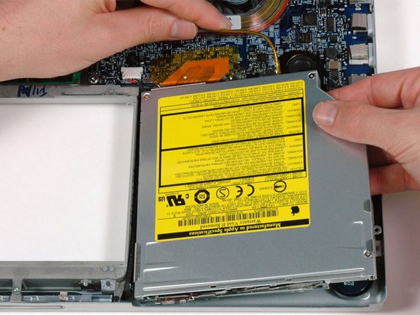
Use one hand to pull back the speaker cable and use your other hand to lift the optical drive up and out of the computer.
-
-
-
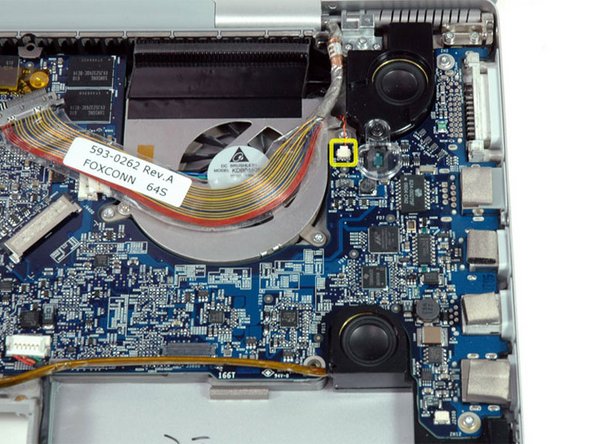
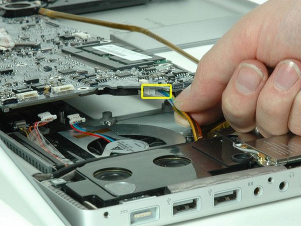
Rotate the large display data cable to the left and disconnect the small right thermal sensor cable beneath.
-
-
-
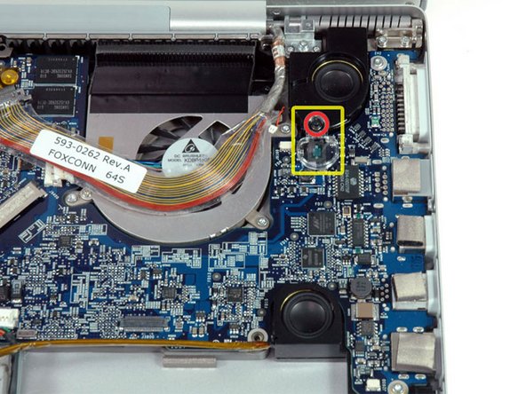
Remove the single black T6 Torx screw securing the clear plastic shield over the right ambient light sensor.
-
Lift the clear plastic shield off the right ambient light sensor.
-
-
-
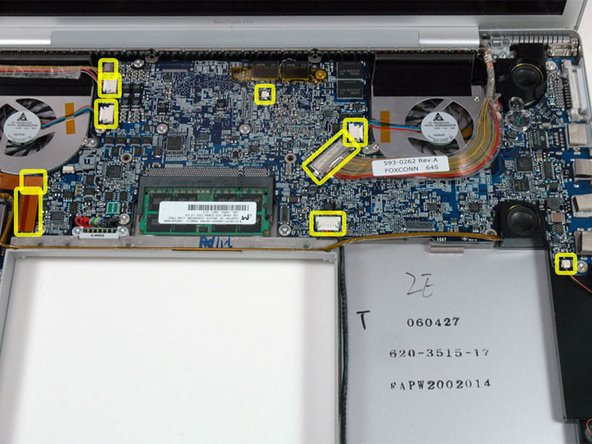
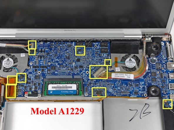
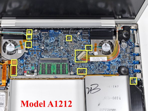
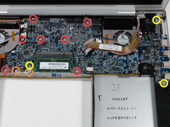
Remove the following twelve screws:
-
Seven 6.5 mm T6 Torx screws.
-
Two 7.6 mm T6 Torx screws securing the battery connector to the lower case.
-
Three 7.8 mm T6 Torx screws.
-
-
-
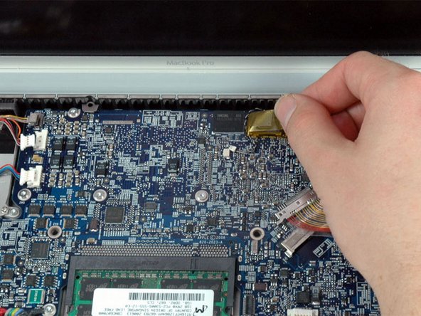
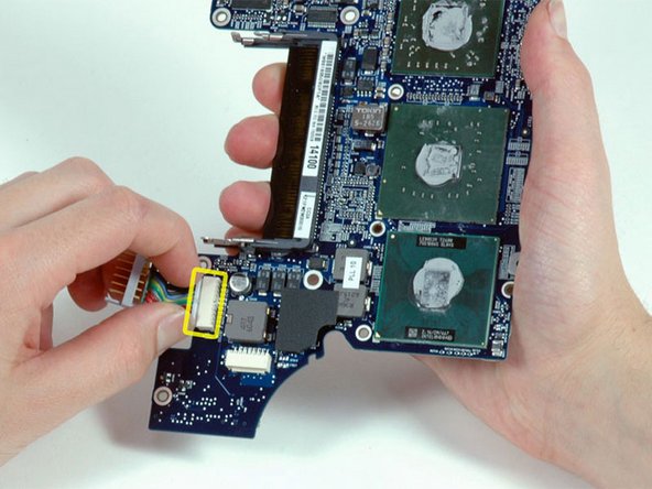
Lift up the left side of the logic board and disconnect the multi-colored power connector from the bottom of the board.
-
-
-
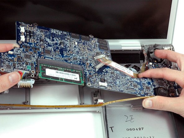
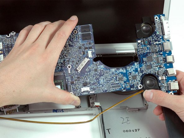
Grasp the logic board at the left side and at the thin section near the right fan, and rotate the logic board out of the lower case.
-
-
-
If the right speaker assembly remains attached to the logic board, hold the logic board with one hand and slide the speaker up slightly to free it from the logic board.
-
-
-
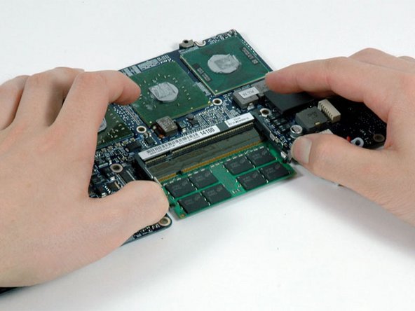
Release the tabs on each side of the RAM chip at the same time. These tabs lock the chip in place and releasing them will cause the chip to "pop" up.
-
Pull the chip directly out from its connector.
-
If there are two RAM chips installed, repeat the above procedure for the second chip.
-


To reassemble your device, follow these instructions in reverse order.
To reassemble your device, follow these instructions in reverse order.
