What you need
-
-
The first step of opening the device is trying to remove the front glass by heating and thus loosening the adhesives that attach the Gorillaglass to the device.
-
In order to flip open the display unit a total of four screws need to be loosened using a #00 screw driver. Then the display unit can be opened up.
-
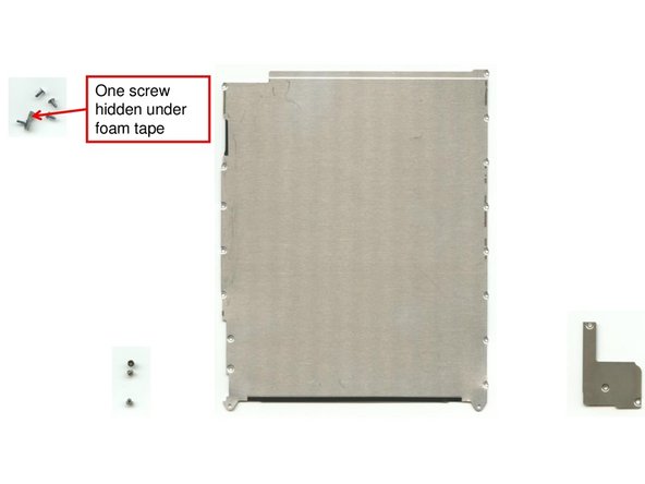
In order two remove the two metal covers a total of 19 screws (#00) need to be removed.
-
After this the display connector, the displayglass connector and the battery connector can be easily unplugged and the display unit be removed.
-
-
-
Once the display unit has been removed and the battery connector has been unplugged, the heat gun has to be used to warm up the adhesives that hold the battery fixed to the device.
-
-
-
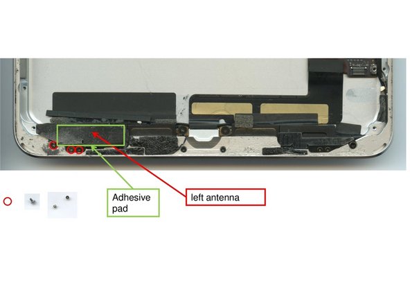
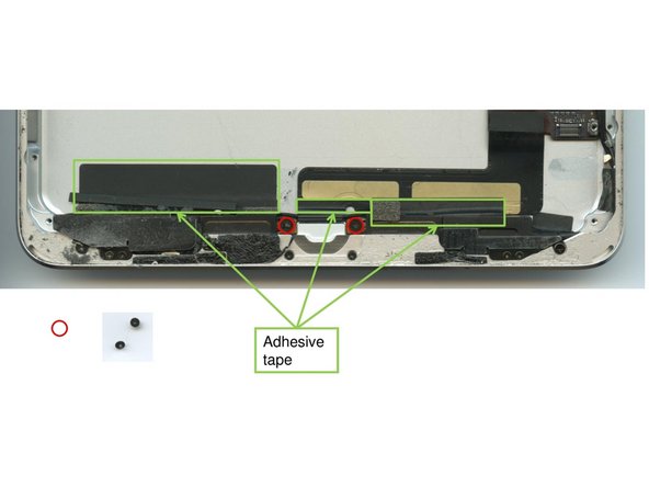
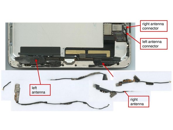
Before extracting the left antenna three screws need to be removed using a #00 screw driver. Additionally the antenna needs to be pulled off a small strip of adhesives.
-
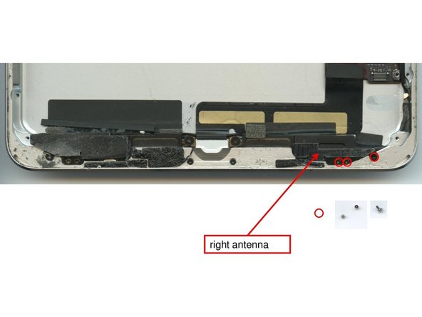
The right antenna is only fixed with three screws (#00) that need to be removed.
-
Before extracting the antennas, first, the speakers need to be removed in Step 4.
-
-
-
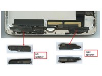
Loosening two screws (#00) in the middle and overcoming the adhesion by levering off the speakers is all you have to do in order to remove the speakers.
-
Both antennas can then be removed by unplugging them from the connectors and extracting them from the device.
-
-
-
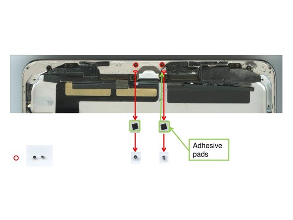
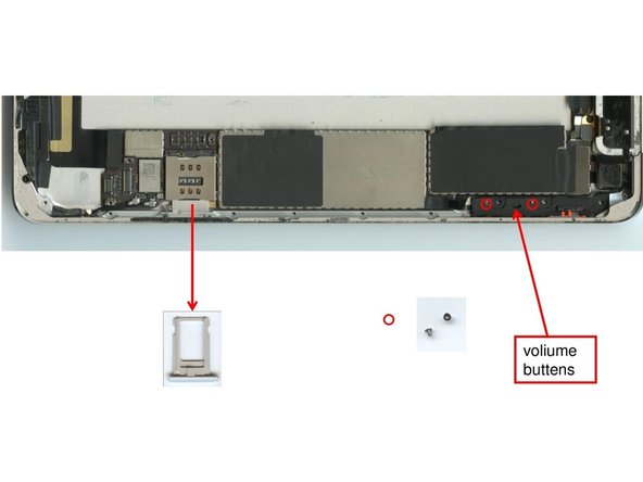
Close to the lightning connector, four screws need to be unscrewed using a #00 screw driver. Two of the screws are located underneath two adhesive pads.
-
-
-
The SD Slot can easily be extracted as it is not fixed with screws or adhesives.
-
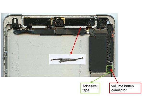
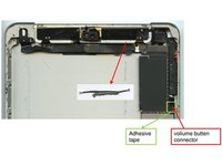
The volume buttons are attached with two little screws (#00). They need to be unscrewed in order to remove them.
-
-
-
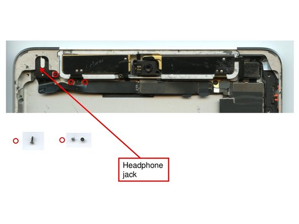
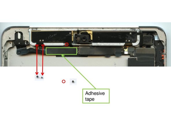
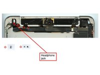
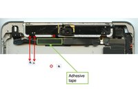
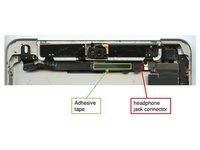
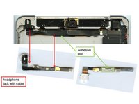
In order to remove the headphone jack five screws (#00) need to be unfastened. One holds down the headphone jack, two fixate the cable horizontally and two screws vertically.
-
There's a sixth screw (#00) next to the camera that may be removed.
-
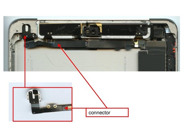
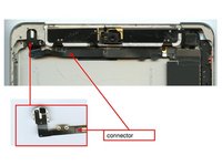
Now it is possible to pull out the headphone jack cable.
-
-
-
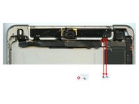
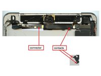
In order to remove the golden modules on the short side of the device where the camera is located as well, you have to pull of the headphone jack first (Step7 ).
-
Remove three screws (#00) that are located close to the right golden module.
-
Both modules can be removed by unplugging their connectors and removing them from the device.
-
-
-
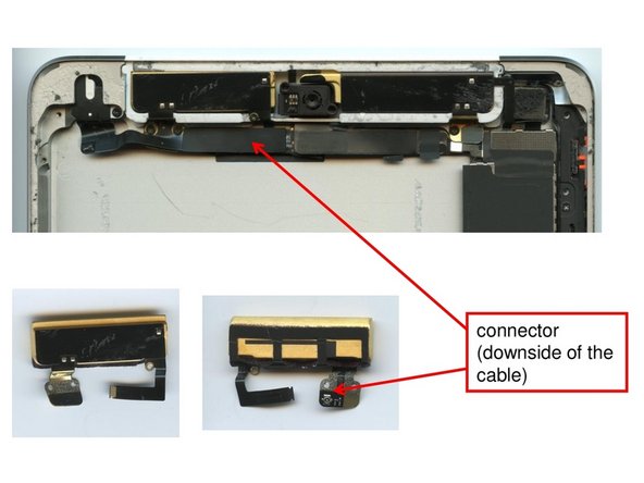
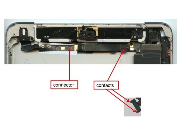
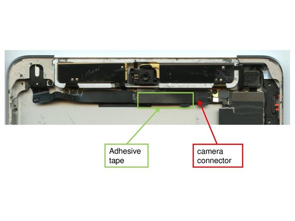
By opening the connector that connects the camera to the mainboard, the first step of removing the front camera is taken.
-
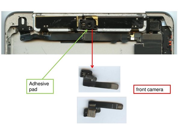
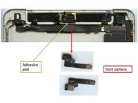
Both the camera cable and the microphone as well as headphone jack cable are connected to each other with adhesives and are also held down to the main board with adhesives. They can be easily separated.
-
Once the cables are unplugged, and the adhesive pads between camera and microphone cable are removed. The front camera can be extracted as well.
-
-
-
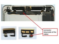
The headphone jack with cable needs to be pulled off the adhesive patches that holds it inside the device.
-
The antenna cable that remains inside the device can also be removed by detaching it from the adhesives at the bottom of the cable.
-
-
-
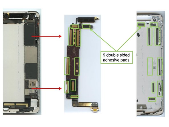
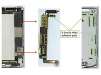
The mainboard is held inside the device by a total of 9 double-sided adhesive pads. the careful use of the lever tool is required to remove the mainboard from the device without destroying it.
-
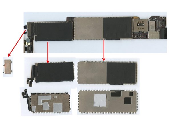
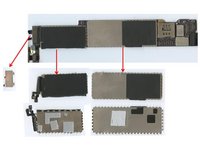
The EMI-shields on the mainboard can be levered off the mainboard using some force. They are attached with adhesives.
-