
What you need
-
-
The SIM Card Holder can be easily removed from its slot.
-
In order to remove the back cover apply the lever tool directly to one of the rubber edges of the device and pry the device open.
-
The back cover is fixed with twenty small plastic clips.
-
-
-
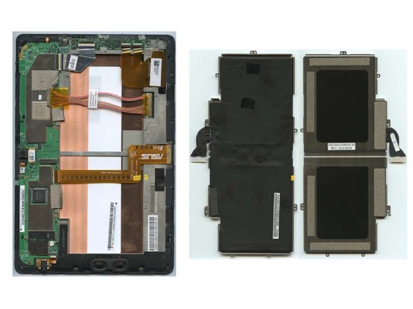
Before removing the battery first seven different adhesives need to be removed that hold down cables.
-
The warranty seal has to be broken and the three connectors unplugged.
-
A total of eight screws (#00) needs to be unscrewed.
-
To remove the battery, first unplug the battery connector to the mainboard. The battery can then be easily removed from the device.
-
-
-
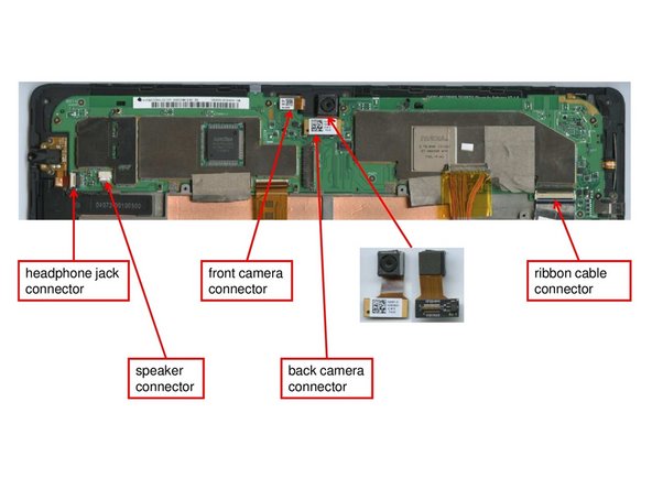
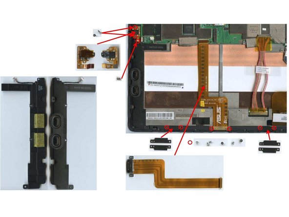
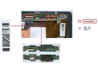
In order to remove the back camera just manually unplug the camera connectors shown in the figure on the left.
-
Manually disconnect the ribbon cables, front camera and headphone jack from the mainboard.
-
-
-
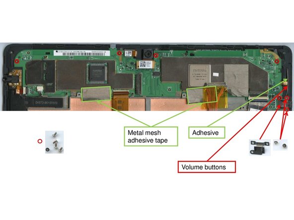
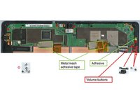
Before removing the mainboard itself, please remove the metal mesh adhesives highlighted in the first figure on the left.
-
To remove the volume buttons, two screws (#00) need to be removed.
-
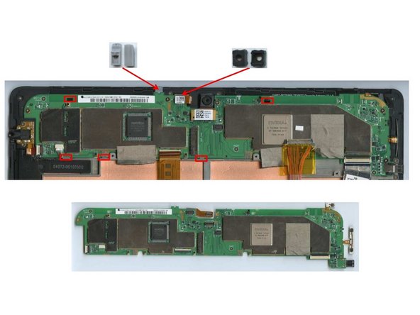
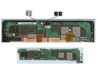
Also, unfasten the five screws (#00) highlighted in the picture that hold down the mainboard.
-
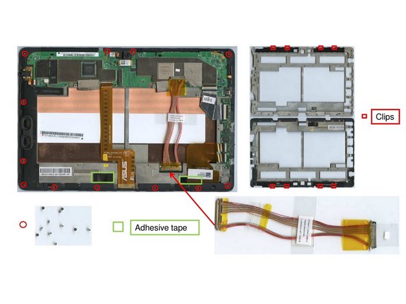
After unscrewing the screws, the mainboard can be removed by detaching it from the 5 clips (figure two) that fixate it.
-
The rubber cover of the microphone and the front camera will simply fall off now.
-
-
-
Remove the two screws (#00)that hold down the headphone jack and after this extract the headphone jack from the device.
-
In order to extract the ribbon cable, again two screws (#00) need to be unfastened that fixate the cable right at the edge of the device.
-
The speaker is fixated with another screw that can be removed using a #00 screw driver.
-
There are two metal parts visible on the frame itself that are fixated with two screws (#00) each, that need to be removed before unscrewing a total of twelve screws that hold down the frame.
-
The magnesium frame itself has an additional four clips that are used to hold it down. They need to be openend before removing the clip.
-
-
-
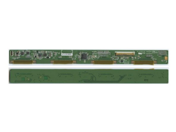
The display board can be removed by destructive means only. First the tape above the display driver board needs to be removed and the board needs to be cut off using a knife or similar tool.
-


Cancel: I did not complete this guide.
One other person completed this guide.