What you need
-
-
In order to open the device, first remove the camera cover. It can be pushed off manually requiring not tool at all.
-
In order to remove the rest of the back cover, one screw has to be removed using a #00 screw driver. NOTE: the screw is located underneath the warranty label.
-
The plastic back cover can then be pulledoff manually.
-
-
-
To remove the plastic frame a total of fifteen screws need to be removed using a #00 screw driver.
-
NOTE: One of the screws is located underneath the label for the serial number.
-
The plastic frame can then be easily removed.
-
-
-
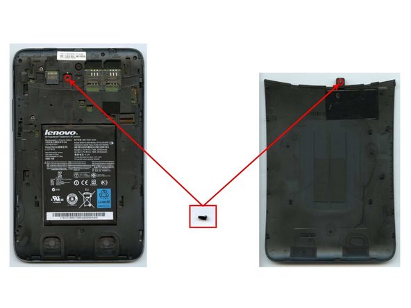
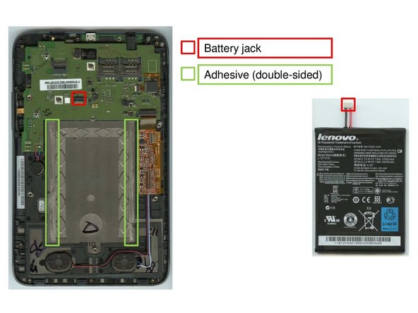
Once the plastic frame is removed, that battery can be extracted by unplugging the battery jack and priying the battery off of two double-sided adhesive patches. This should not pose a problem.
-
-
-
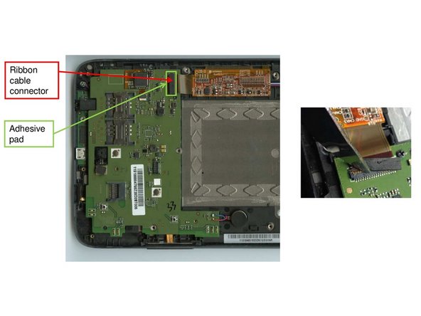
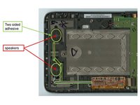
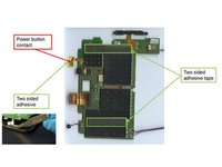
Removing the main components on the mainboard starts with opening the ribbon cable connector in figure one. It is attached to the mainboard with a small two-sided adhesive that can be levered off easily.
-
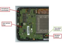
Removing the speakers, the vibration module and the microphone requires similar little effort. Just find the components and remove them using a small lever tool.
-
-
-
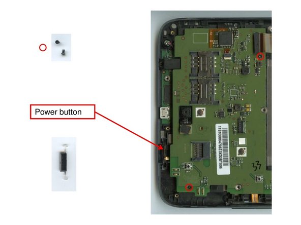
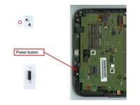
Before removing the mainboard, first loosen the two screws indicated in figure one using a #00 screw driver.
-
The power button located on the edge of the device can be extracted manually.
-
The mainboard can now be removed easily. It is only attached to the device with two small adhesive patches.
-
-
-
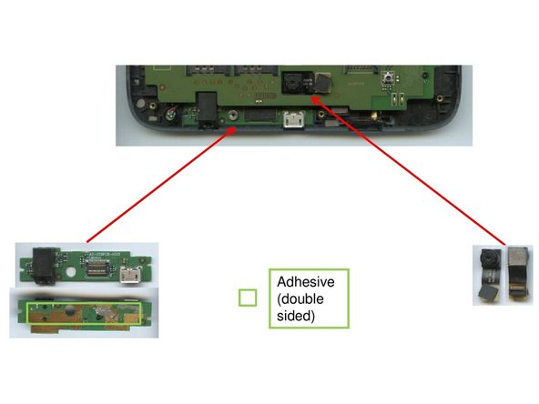
Both the usb/headphone board and the rear camera are attached to the device using only weak adhesives that can be levered off without problem.
-
-
-
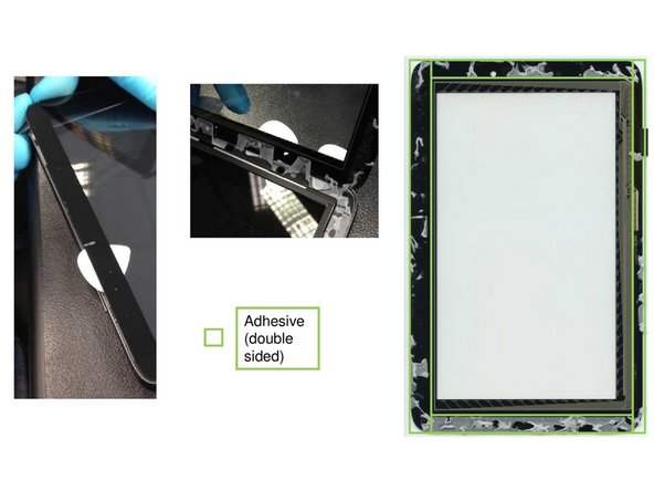
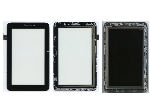
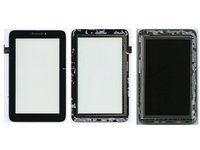
In order to separate display and frame, a strong lever is required. Adhesives along the frame form a strong bond between display and frame that needs to be destoyed.
-
NOTE: When trying to keep the display cable intact. You need to carefully lift it through the frame. Otherwise it will tear.
-