
Introduction
Use this guide to replace a broken AirPort/Bluetooth board to regain wireless capability.
What you need
-
-
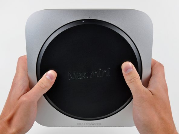
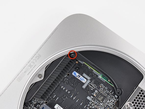
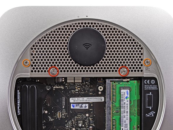
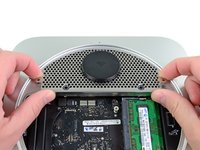
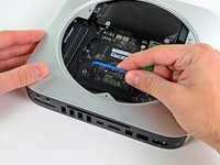
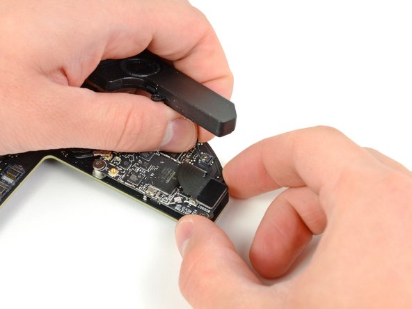
Place your thumbs in the depressions cut into the bottom cover.
-
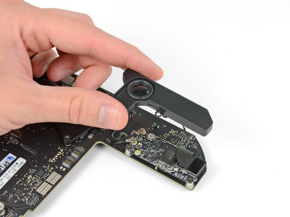
Rotate the bottom cover counter-clockwise until the white dot painted on the bottom cover is aligned with the ring inscribed on the outer case.
-
-
-
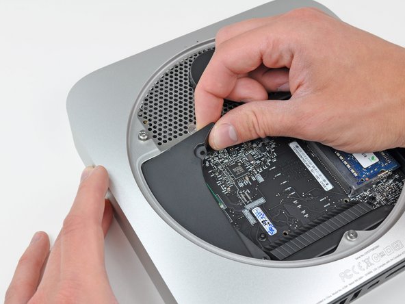
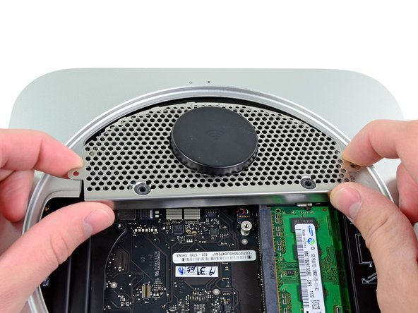
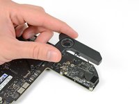
Tilt the mini enough to allow the bottom cover to fall away from the outer case.
-
Remove the bottom cover and set it aside.
-
-
-
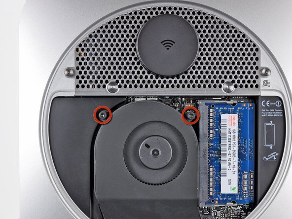
Remove the two 11.3 mm T6 Torx screws securing the fan to the logic board near the antenna plate.
-
-
-
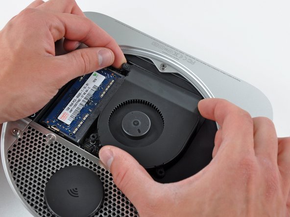
Lift the fan out of the mini for enough clearance to access its connector.
-
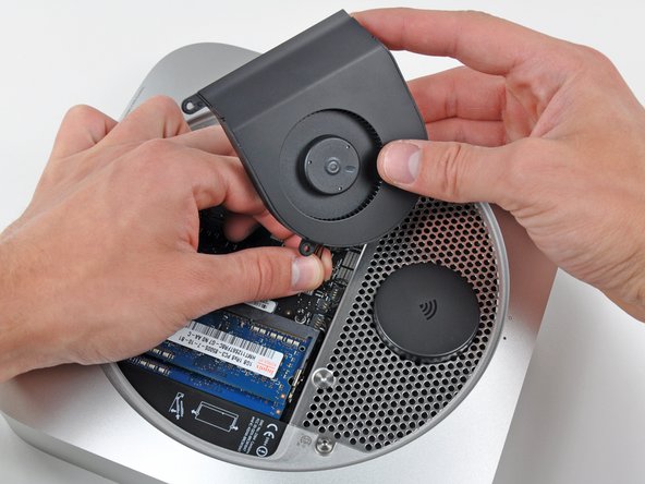
Carefully pull the fan cables upward to lift the fan connector up out of its socket on the logic board.
-
Remove the fan.
-
-
-
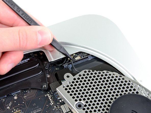
Lift the cowling from the end nearest the antenna plate.
-
Rotate the cowling away from the outer case and remove it from the mini.
-
-
-
Remove the following screws securing the antenna plate to the mini:
-
Two 6.6 mm T8 Torx screws
-
Two 5.0 mm T8 Torx or 2.0 mm Hex screws (either screwdriver will work)
-
When putting back together:
-
-
-
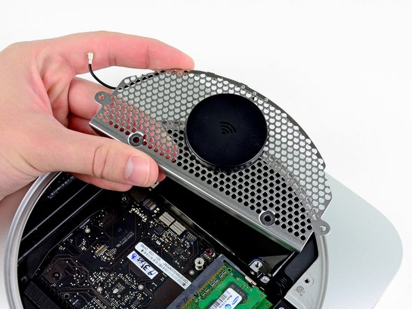
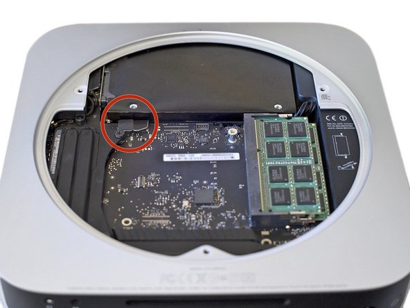
Slightly lift the antenna plate from the end closest to the RAM.
-
Carefully pull the antenna plate away from the circular rim of the outer case.
-
-
-
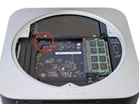
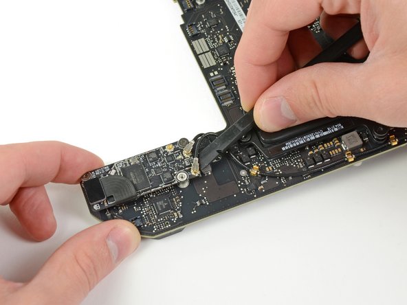
Use the tip of a spudger to carefully pry the antenna connector up from its socket on the AirPort/Bluetooth board.
-
-
-
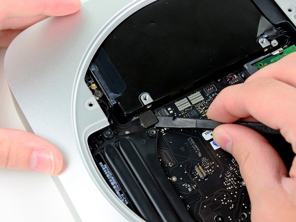
Use the flat end of a spudger to pry the hard drive connector up from its socket on the logic board.
-
-
-
Use the tip of a spudger to lift the IR sensor connector up and out of its socket on the logic board.
-
-
-
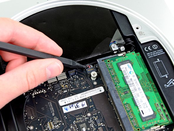
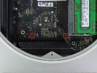
Remove the following three screws:
-
One 5.0 mm T8 Torx or 2.0 mm Hex screw (either screwdriver will work)
-
One 16.2 mm T6 Torx screw
-
One 26 mm T6 Torx standoff
-
-
-
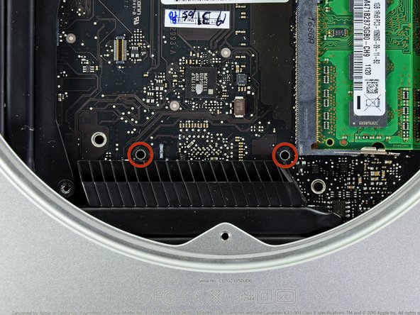
Insert the into the two holes highlighted in red. Be sure it makes contact with the top side of outer case below the logic board before proceeding.
-
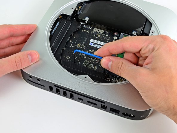
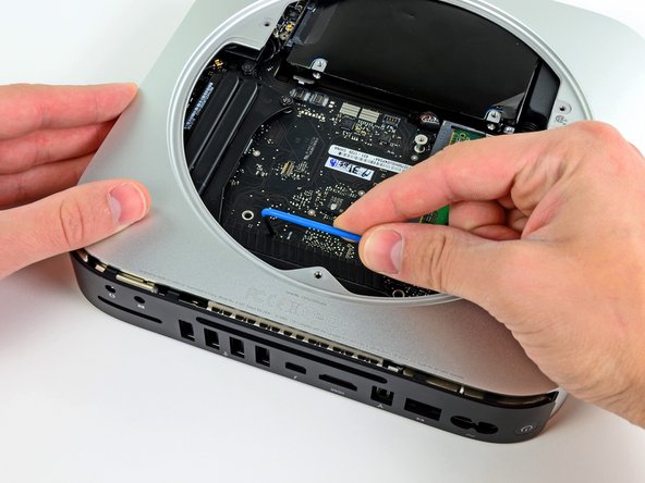
Carefully pull the tool toward the I/O board. The logic board and I/O board assembly should slightly slide out of the outer case.
-
Remove the Mac Mini Logic Board Removal tool.
-
-
-
Pull the I/O board/logic board assembly out of the outer case enough to access the power connector.
-
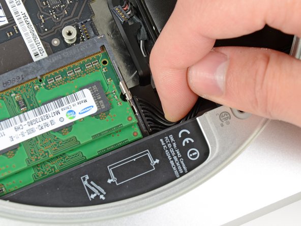
Use your fingers to disconnect the DC-In cable from the logic board.
-
Pull the power cable connector toward the front side of the mini.
-
-
-
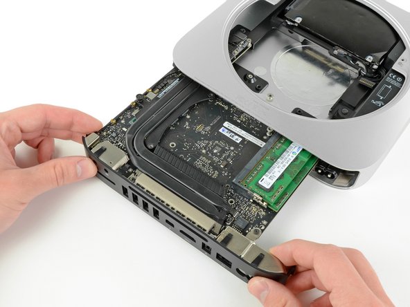
Carefully slide the logic board assembly out of the mini, minding any cables that may get caught.
-
-
-
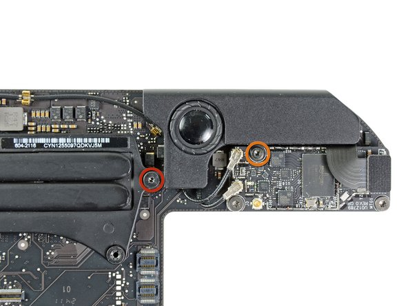
Remove the following two screws securing the speaker to the logic board assembly:
-
One 3.5 mm T6 Torx screw
-
One 3.7 mm T6 Torx screw
-
-
-
Carefully lift the speaker wires upward to lift the speaker connector up and out of its socket on the logic board.
-
Lift and remove the speaker away from the logic board.
-
-
-
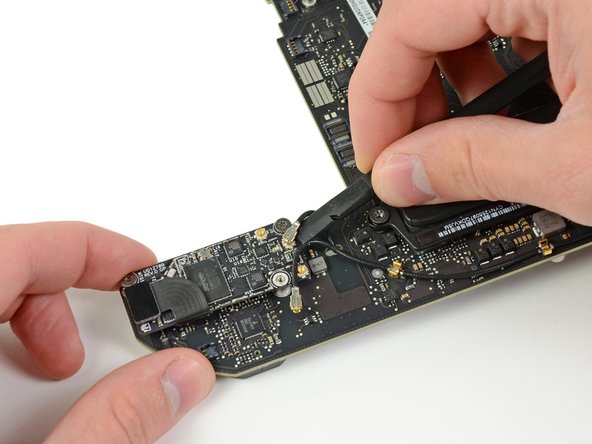
Use the flat end of a spudger to pry both antenna connectors up from their sockets on the AirPort/Bluetooth board.
-
-
-
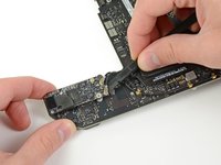
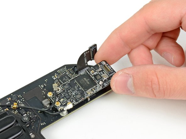
Use your spudger to help disconnect the AirPort/Bluetooth ribbon cable from its socket on the AirPort/Bluetooth board.
-
-
-
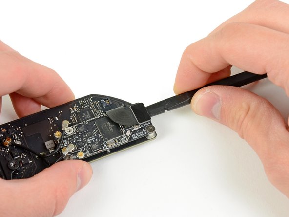
Remove the two 2.6 mm T6 Torx screws securing the AirPort/Bluetooth board to the logic board.
-


To reassemble your device, follow these instructions in reverse order.
