
Introduction
This guide will show you how to replace the logic board.
What you need
-
-
You'll need a putty knife in order to open the case. A 1.5 inch thin putty knife will work well, but you'll want to grind the edge down. Rub the putty knife's short edge back and forth on a sheet of all purpose rough grit sandpaper (100 grit will work fine) until it attains a beveled edge.
-
-
-
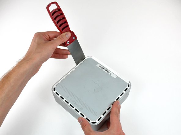
Carefully insert a putty knife into the crevice in between the top cover and bottom housing. Start on the left side first. Push the blade down until you meet firm resistance (roughly 3/8 of an inch).
-
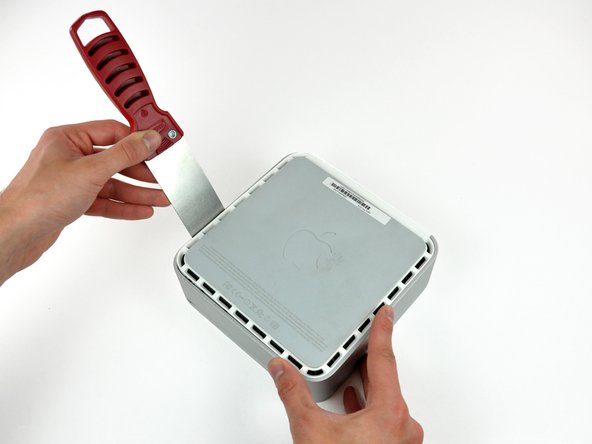
Gently enlarge the existing crevice by prying the handle of the putty knife downward and away from the mini.
-
-
-
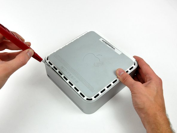
Next insert the putty knife into the crevice on the optical drive slot side of the computer.
-
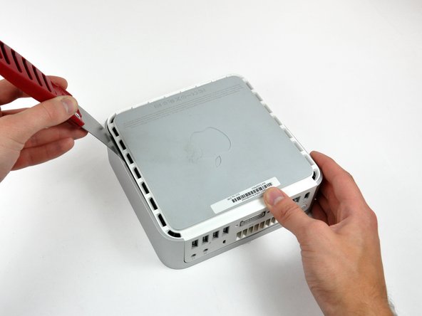
Pry the putty knife downward while working along the edge of the mini until the bottom housing further separates from the top housing.
-
-
-
Repeat the same procedure as the past few steps for the right side of the mini.
-
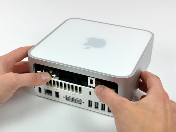
Turn the mini over.
-
-
-
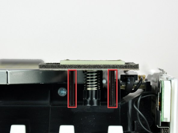
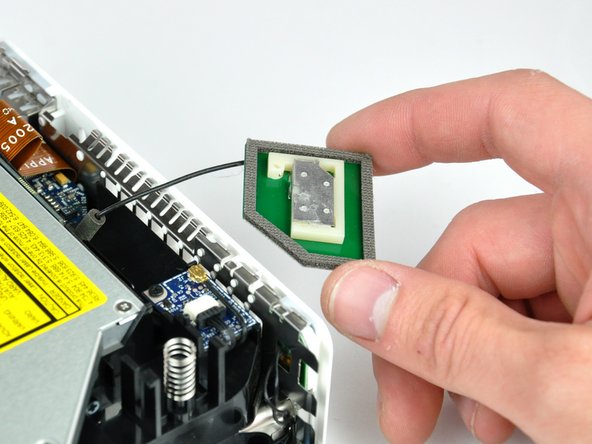
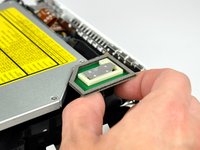
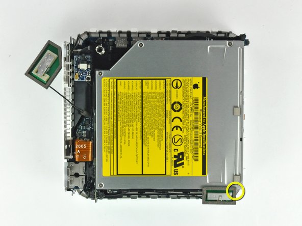
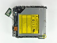
Slightly squeeze the two retaining arms toward each other and lift the AirPort antenna off its post.
-
-
-
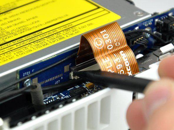
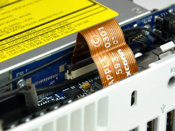
Use the tip of a spudger to slightly lift the left side of the ZIF cable lock up from its socket.
-
-
-
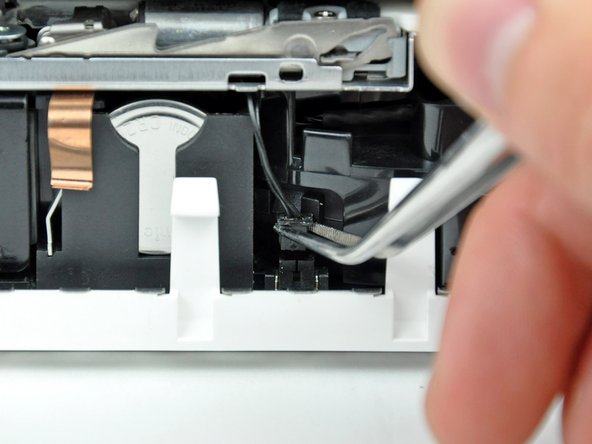
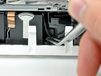
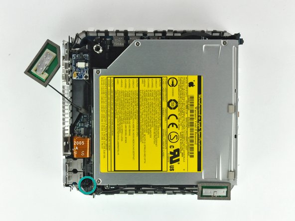
Use a pair of tweezers to lift the hard drive thermal sensor cable connector up off its socket on the logic board.
-
-
-
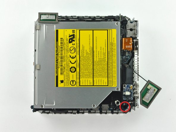
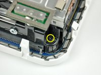
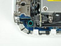
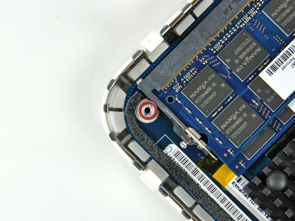
Remove the recessed Phillips screw near the power button securing the internal frame to the bottom housing.
-
-
-
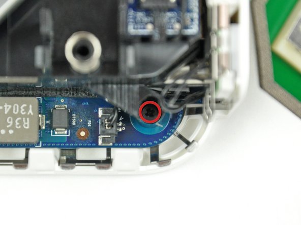
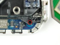
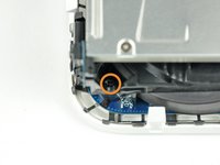
Remove the recessed Phillips screw near the sleep light securing the internal frame to the bottom housing.
-
-
-
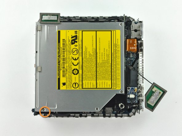
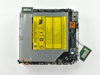
Remove the Phillips screw near the audio ports securing the internal frame to the bottom case.
-
-
-
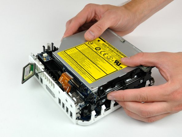
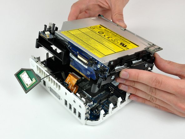
Gently lift the internal frame up from the bottom housing, minding the AirPort antenna and any other cables that may get caught.
-
-
-
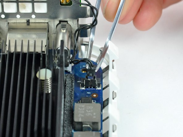
Firmly grasp the power button cable connector with a pair of tweezers and lift it straight up off the logic board.
-
-
-
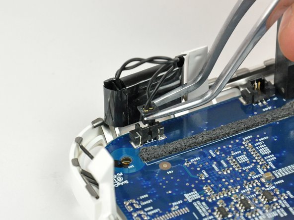
Firmly grasp the sleep light cable connector with a pair of tweezers and lift it straight up off the logic board.
-
-
-
Use the flat end of a spudger to slightly lift the logic board near the PRAM battery to separate it from the bottom housing.
-
-
-
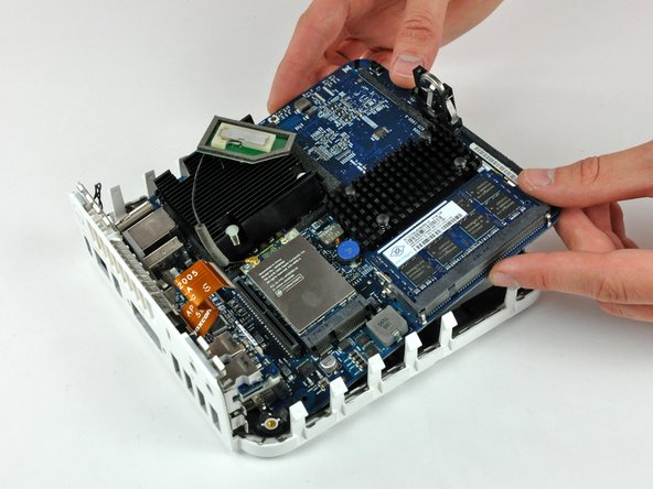
Gently lift the free end of the logic board and wiggle the board as you pull it away from the I/O ports.
-
-
-
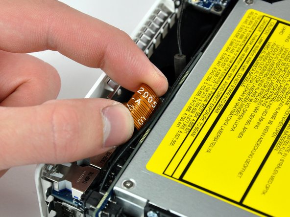
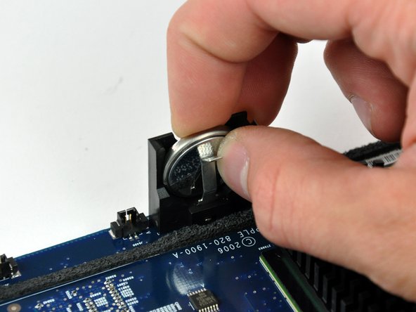
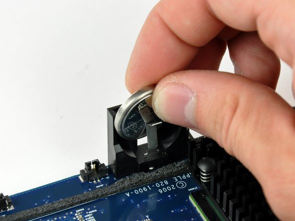
Push the PRAM battery toward the center of the logic board and pull it up out of its holder. You'll have to push the battery in further than you'd expect in order to get it to pop free.
-
When inserting the new battery, make sure the side with writing along the edges faces the black plastic holder. You should also ensure that the metal connectors make contact with the battery (you can bend them forward if they do not).
-
-
-
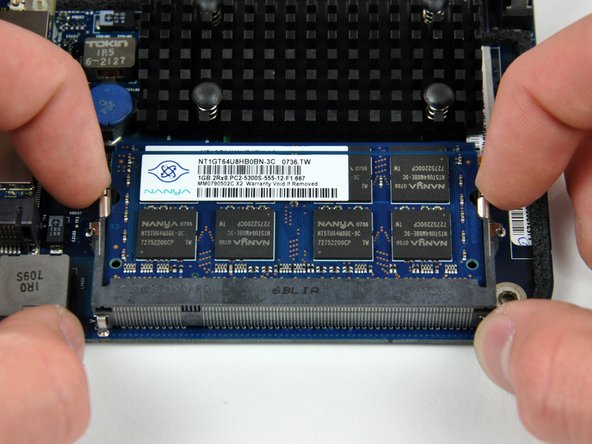
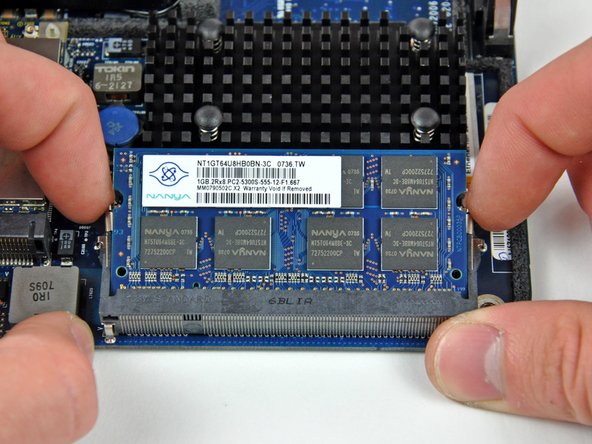
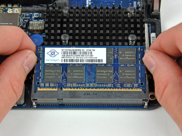
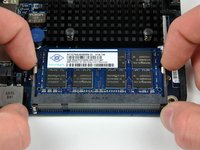
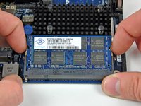
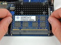
Simultaneously pull the tabs on each side of the RAM chip away from the center of the chip. These tabs lock the chip in place and releasing them will cause the chip to "pop" up.
-
Pull the RAM chip directly out from its connector.
-
-
-
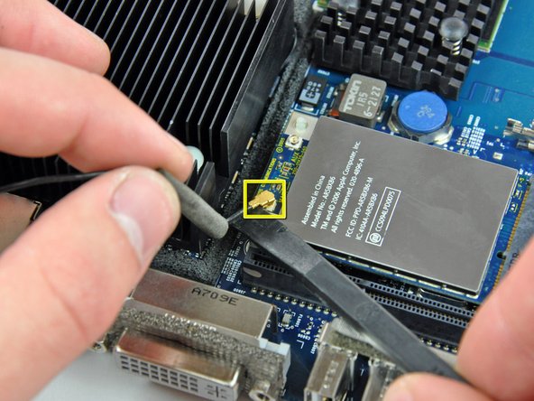
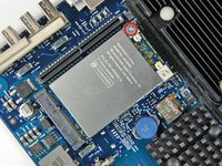
Use the flat end of a spudger to pry the AirPort antenna cable connector up off the AirPort card.
-
-
-
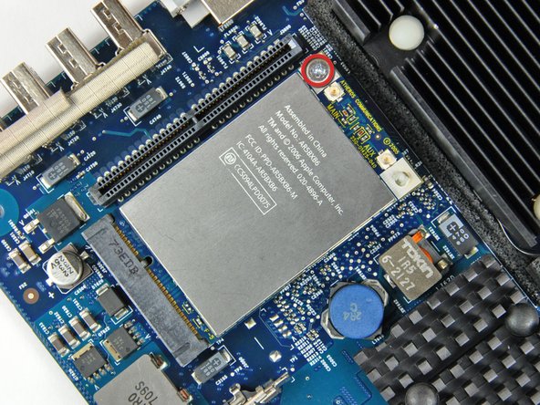
Remove the single Phillips screw securing the AirPort card to the logic board.
-
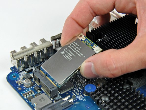
Pull the AirPort card away from its socket on the logic board.
-


To reassemble your device, follow these instructions in reverse order.
