MacBook Air 13" Late 2010 I/O Board Cable Replacement

What you need

    1. MacBook Air 13" Late 2010 I/O Board Cable Replacement, MacBook Air 13" Late 2010 I/O Board Cable Replacement: step 1, image 1 of 1
      • Before proceeding, close your computer and lay it on a soft surface top-side down.

      • Remove the following ten screws:

      • Two 9 mm 5-point Pentalobe screws

      • Eight 2.6 mm 5-point Pentalobe screws

      • The special screwdriver needed to remove the eight 5-point Pentalobe screws can be found .

      Add Comment

    2. MacBook Air 13" Late 2010 I/O Board Cable Replacement: step 2, image 1 of 1
      • Wedge your fingers between the display and the lower case and pull upward to pop the lower case off the Air.

      • Remove the lower case and set it aside.

      Add Comment

    3. MacBook Air 13" Late 2010 I/O Board Cable Replacement: step 3, image 1 of 1
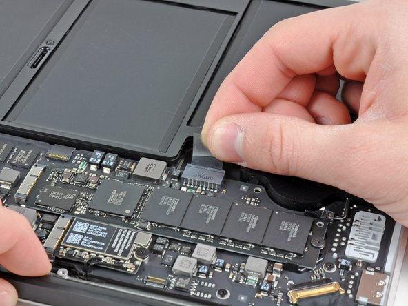
      • For precautionary purposes, we advise that you disconnect the battery connector from the logic board to avoid any electrical discharge. This step is optional and is not required.

      • Grab the clear plastic pull tab attached to the battery connector and pull it toward the front edge of the Air to disconnect the battery from the logic board.

      • Do not lift upward on the connector as you disconnect it.

      Add Comment

    4. MacBook Air 13" Late 2010 I/O Board Cable Replacement: step 4, image 1 of 1
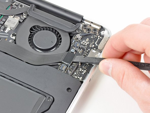
      • Use the flat end of a spudger to pry the I/O board cable connector upward out of its socket on the I/O board.

      Add Comment

    5. MacBook Air 13" Late 2010 I/O Board Cable Replacement: step 5, image 1 of 2 MacBook Air 13" Late 2010 I/O Board Cable Replacement: step 5, image 2 of 2
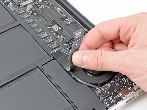
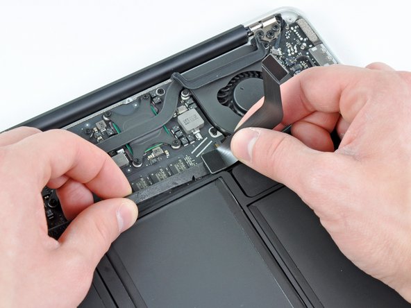
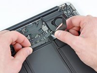
      • The following connector has an especially deep socket. Use care when disconnecting it.

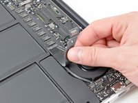
      • Carefully peel the I/O board cable from the top of the fan.

      • While gently pulling the I/O board cable upward near its connection to the logic board, use the tip of a spudger to pry upward on alternating sides of the connector to help "walk" it out of its socket.

      • Remove the I/O board cable.

      Add Comment

Conclusion

To reassemble your device, follow these instructions in reverse order.

Cancel: I did not complete this guide.

System

Member since: 09/24/09

2,562 Guides authored

0 Guide Comments

Add Comment

View Statistics:

Past 24 Hours: 0

Past 7 Days: 0

Past 30 Days: 0

All Time: 11