
Introduction
Replacing the plastic bottom case.
What you need
-
-
Use a coin to rotate the battery-locking screw 90 degrees clockwise.
-
-
-
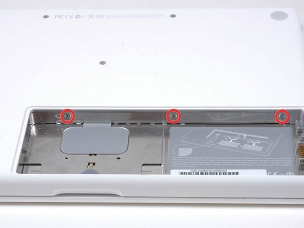
Unscrew the three evenly-spaced Phillips screws from along the rear wall of the battery compartment.
-
-
-
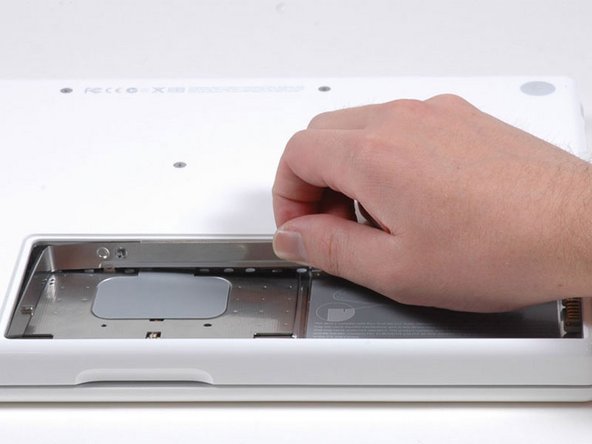
Rotate the L-shaped memory cover so it clears the battery compartment opening and lift it up and out of the computer.
-
-
-
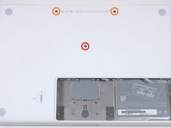
Remove the following 3 screws:
-
One 11 mm Phillips#00 in the middle of the case. (Head: 5mm dia. x .75mm thick)
-
Two 14.5 mm Phillips #00 (Head: 5mm dia. x .75mm thick)
-
-
-
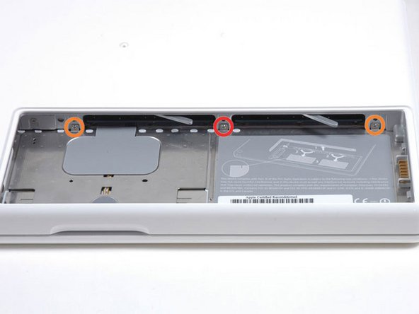
Remove the following 3 screws from the rear wall of the battery compartment:
-
One 3 mm Phillips #0. (Head: 2.75 mm. dia.)
-
Two 4 mm Phillips #0 on the either side. (Head: 2.75mm dia.)
-
-
-
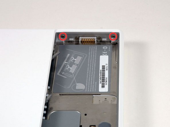
Remove the two Phillips screws from either side of the right wall of the battery compartment (not the ones closest to the battery connector).
-
Two 6.25 mm Phillips #000. (Head: 4 mm. dia. x .5mm thick)
-
-
-
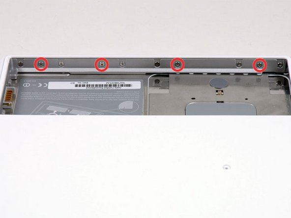
Remove the four indicated Phillips screws from the front wall of the battery compartment. When working from the left, remove the 2nd, 4th, 7th and 9th screw.
-
Four 3.25 mm Phillips #000. (Head: 4 mm. dia. x 4mm thick)
-
-
-
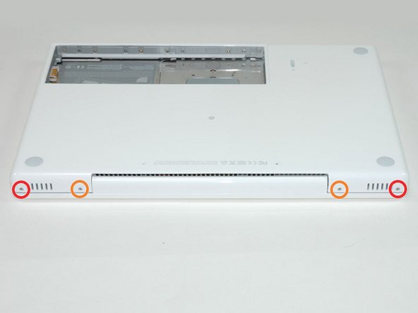
Remove the following 4 screws from the back of the computer:
-
The longer screws go on the inside, shorter screws on the outside.
-
Two 11 mm Phillips #00, with Shank (2.2mm dia. x 2 mm len.) (Head: 3.2 mm. dia. x .5mm thick)
-
Two 7.25 mm Phillips #00, with Shank (2mm dia. x 3.75 mm len.) (Head: 3.2 mm. dia. x .5mm thick)
-
-
-
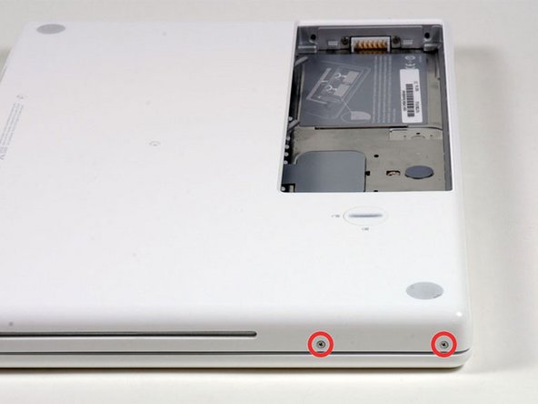
Remove the two Phillips screws from the optical drive side of the computer.
-
Two 5.2 mm Phillips #00, with Shank (2.3mm dia. x 3.5 mm len.) (Head: 3.2 mm. dia. x .5mm thick)
-
-
-
Starting near the display and working around to the front of the computer, pry up on the upper case. A or a medium hard guitar pick may help you to do this.
-
-
-
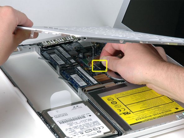
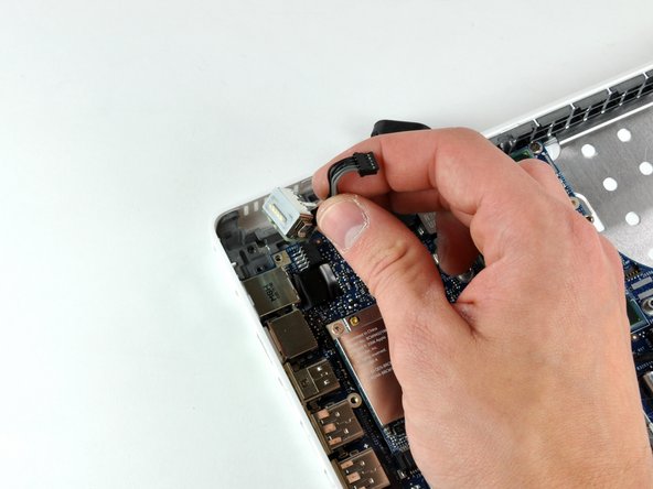
While holding up the upper case, pull up the black tab of the silver cable away from its connector.
-
While you have the upper case removed, you may want to take the opportunity to remove dust, hair, etc. It's best to use a can of compressed air, though if you use a brush, make sure that its bristles are made of a material (usually animal hair) that doesn't generate static electricity, which can destroy electronics.
-
-
-
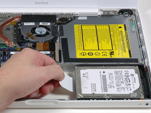
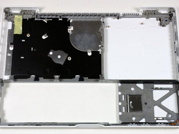
Grasp the white plastic tab attached to the hard drive and pull it to the left, removing the hard drive from the computer.
-
-
-
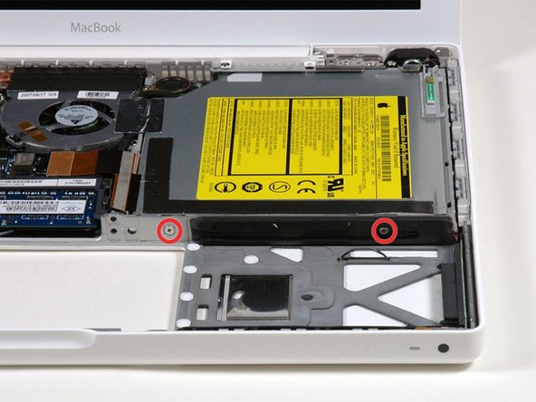
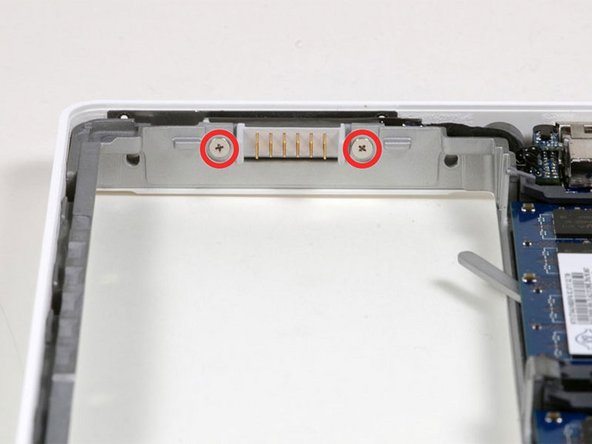
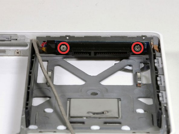
Remove the two Phillips screws from the front edge of the optical drive.
-
Two 3.25 mm Phillips #000, (Head: 4 mm. dia. x .3 mm thick)
-
-
-
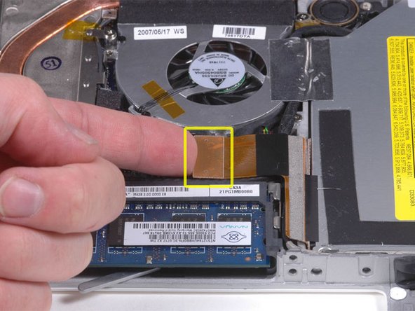
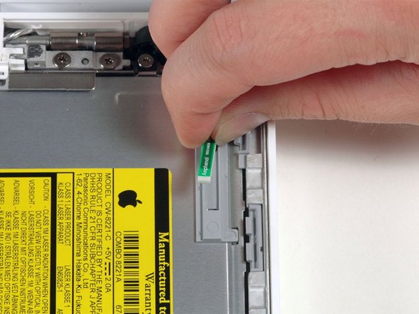
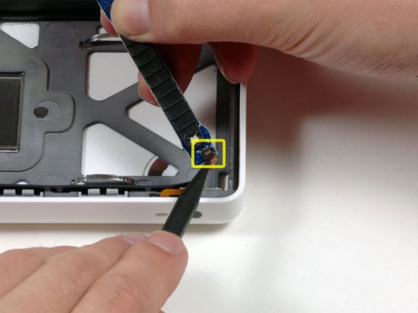
Disconnect the orange optical drive ribbon cable from the logic board. This cable can also be disconnected by prying straight up using a spudger.
-
-
-
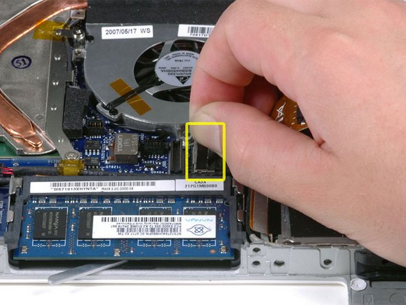
Disconnect the newly revealed display data cable. If there is no pull-tab on the top of the connector, it may be helpful to use a spudger to disconnect this connector.
-
-
-
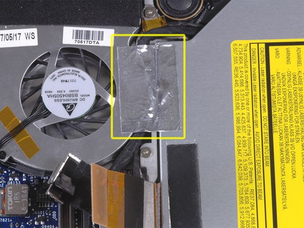
Peel up the foil tape between the fan and the optical drive. Lift the foil tape from the fan side, leaving it attached to the optical drive.
-
During reassembly, be sure to route the cables beneath the tape before reattaching it.
-
-
-
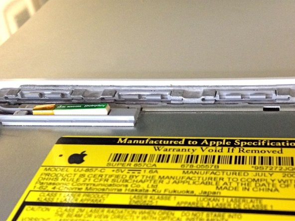
Pull up the display data cable from along the edge of the optical drive to reveal a silver Phillips screw.
-
-
-
Remove the 2 mm Phillips #00 screw securing the optical drive.
-
The Bluetooth cable may be covering the screw. If so, carefully push it aside. You may need to unscrew the cable clip to free the cable enough.
-
-
-
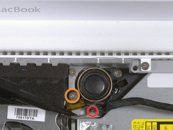
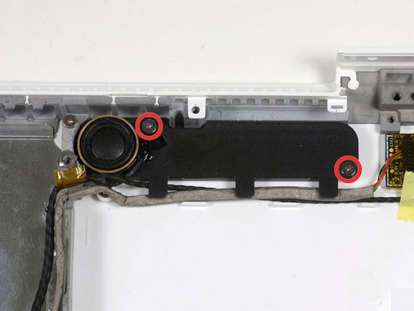
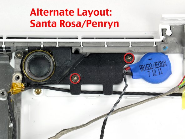
Remove the following 3 screws:
-
Two 3 mm Phillips near the right speaker.
-
One 6 mm Phillips threaded through a hole in a plastic finger above the subwoofer.
-
-
-
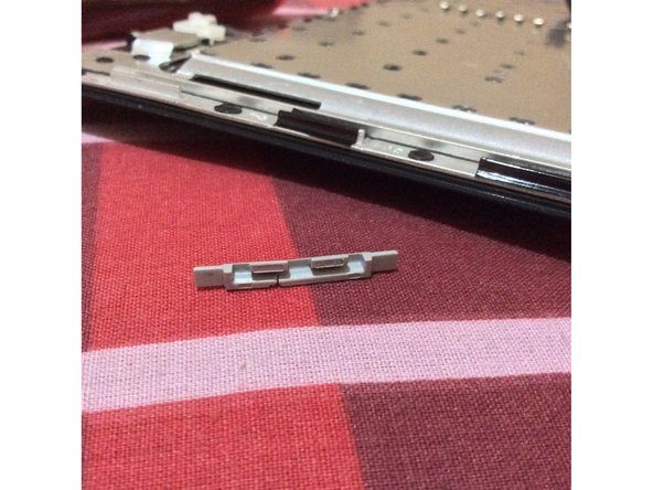
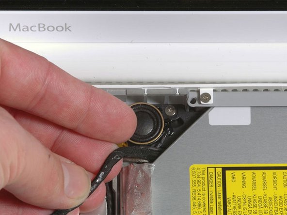
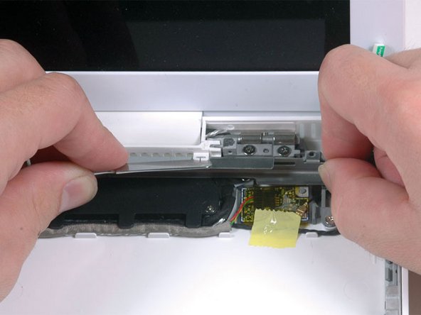
Using a spudger, gently pry up the white plastic slot and slide the metal c-channel to the right and away from the display.
-
-
-
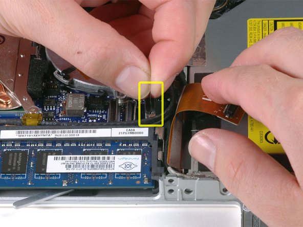
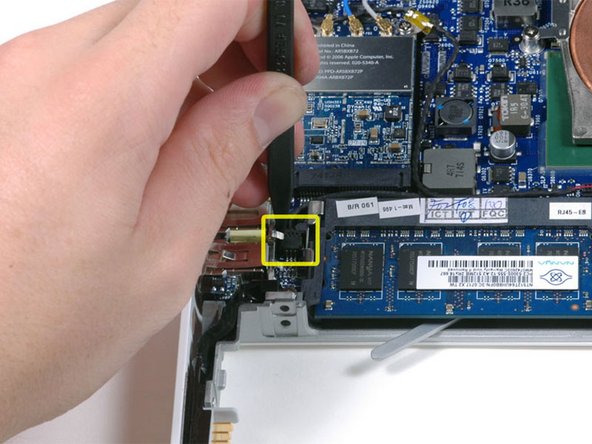
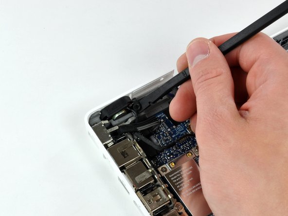
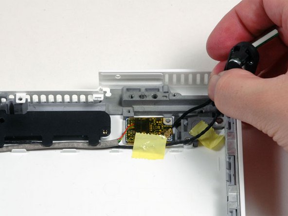
Use a spudger to carefully disconnect the microphone cable from the logic board. You'll want to work from side to side, and slowly wiggle the connector out of its socket.
-
-
-
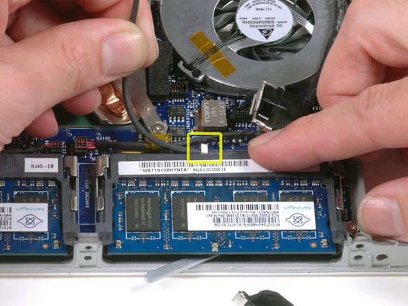
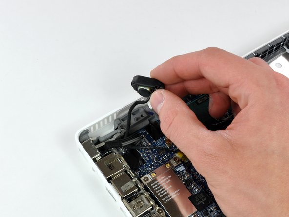
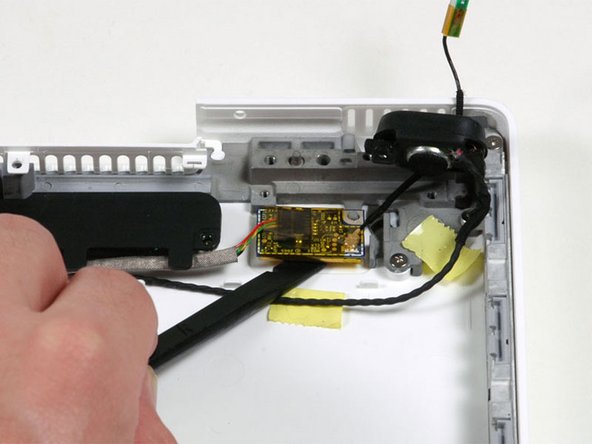
Lift up on the black right speaker cable with one hand, and deroute the microphone cable from the silver metal clip just above the right RAM slot.
-
-
-
If you didn't remove the ground loop screw in step 20 above, remove it now. It's a 7 mm (may be 4.2 mm in Santa Rosa/Penryn models) Phillips screw securing the ground loop in the right speaker cable and microphone cable to the metal framework.
-
-
-
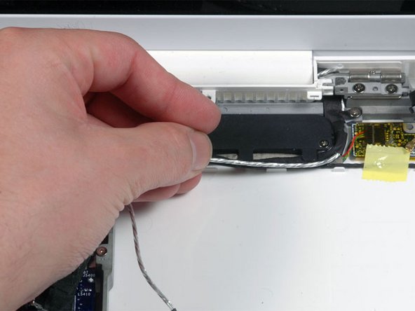
Deroute the microphone cable and the black display data cable from the tabs at the bottom of the subwoofer.
-
-
-
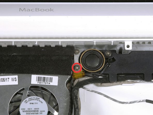
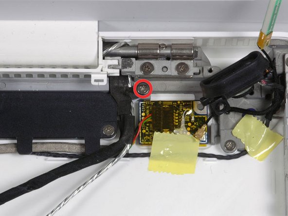
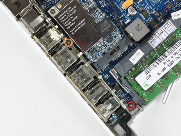
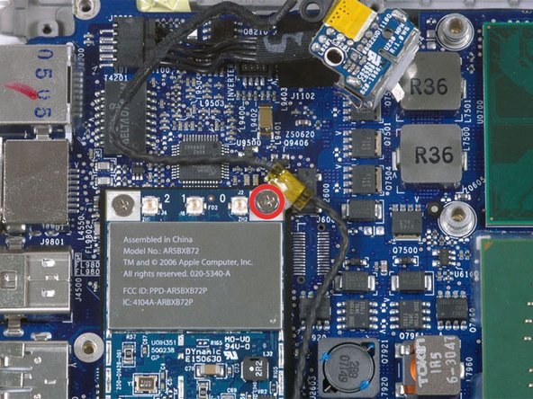
Remove the single 3 mm Phillips screw securing the ground loop in the display data cable located just above the Bluetooth board.
-
-
-
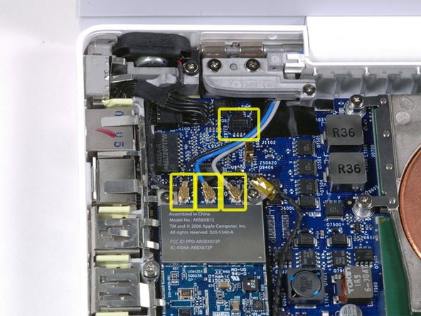
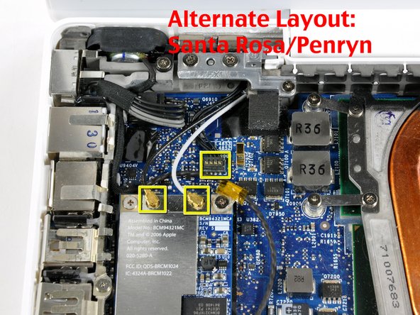
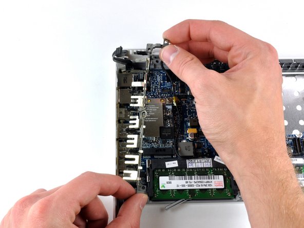
Disconnect the three antenna cables from the Airport card. There may be a square foam piece over the logic board connector.
-
-
-
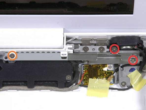
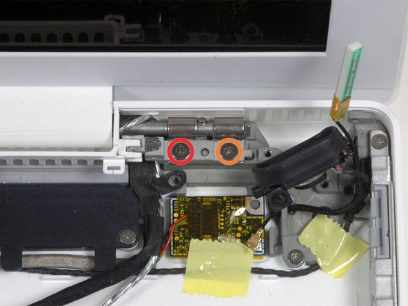
Remove the following 2 screws from the right hinge mount:
-
One 6 mm Phillips on the left side of the hinge mount.
-
One 10 mm Phillips on the right side of the hinge mount.
-
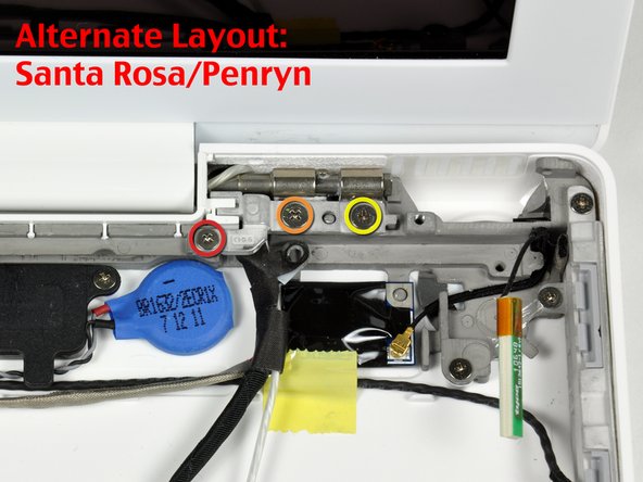
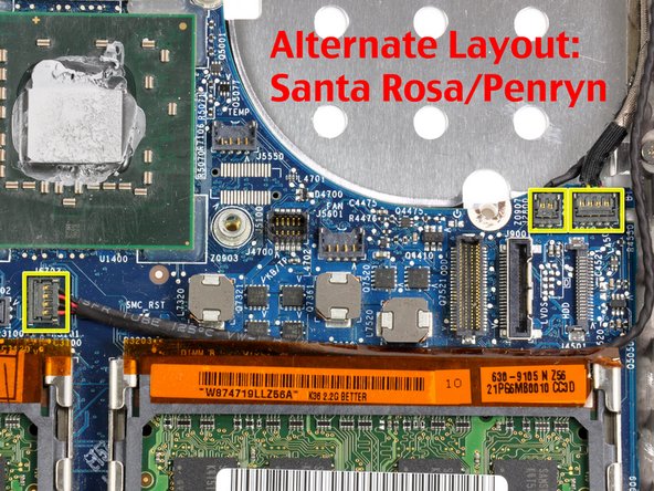
For Santa Rosa/Penryn models, see second picture and remove:
-
One 3 mm smalller diameter Phillips on the far left.
-
One 5.2 mm larger diameter 4.2 mm head Phillips in the middle.
-
One 10 mm Phillips from the far right.
-
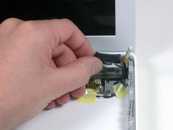
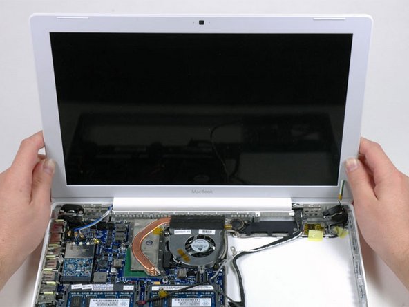
Lift the right hinge mount with the small plastic piece out of the computer.
-
-
-
Hold the display with one hand while removing the screws from the left hinge mount.
-
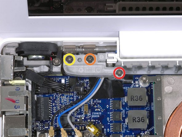
Remove the following 3 screws from the left hinge mount:
-
One 7.2 mm smaller diameter Phillips from the right side.
-
One 5.2 mm larger diameter Phillips from the middle.
-
One 10 mm Phillips from the left side.
-
Lift the left hinge mount with plastic piece out of the computer.
-
Check that the cables on the right are not trapped under other cables.
-
-
-
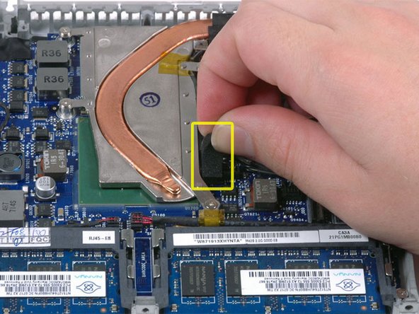
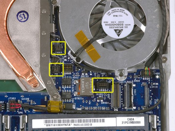
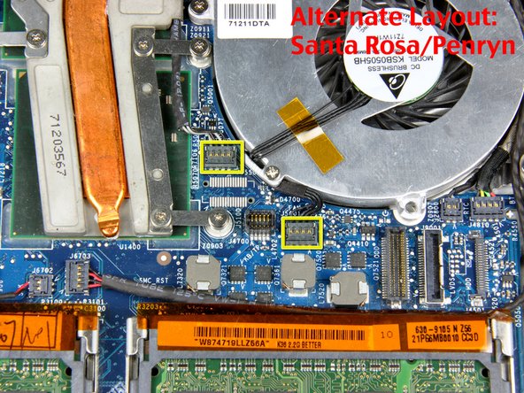
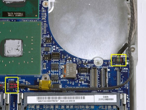
Disconnect the two newly-revealed temperature sensor connectors and the fan connector from the logic board. These connectors move up, not towards the rear of the case, and can be lifted with gentle pressure from under the cable.
-
-
-
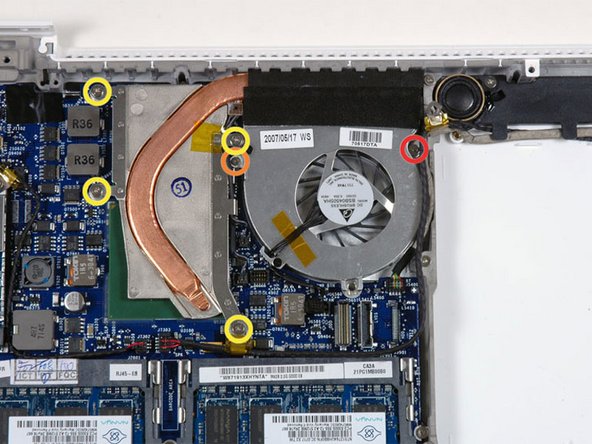
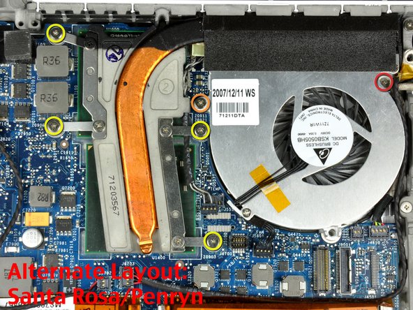
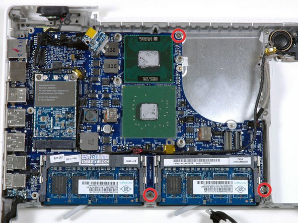
Remove the following 6 screws:
-
One 3 mm Phillips on the right side of the fan.
-
One 6 mm Phillips on the left side of the fan.
-
Four 9 mm Phillips securing the heat sink to the lower case.
-
On Santa Rosa/Penryn models, the heat sink has a slightly different bolt pattern. See second picture.
-
-
-
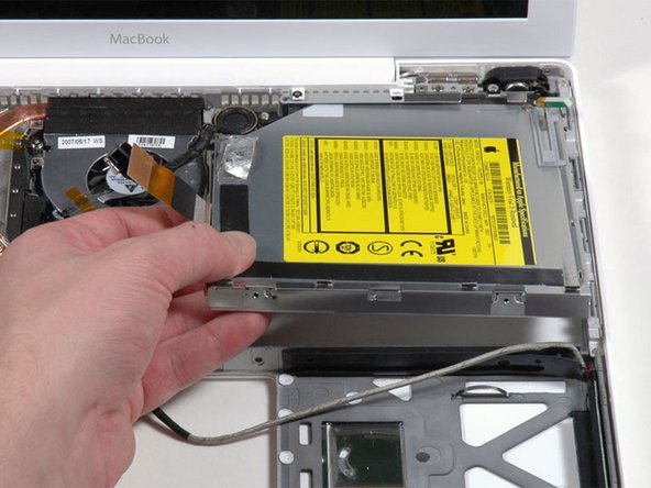
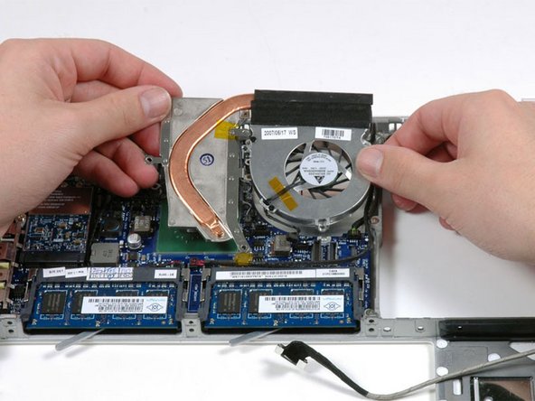
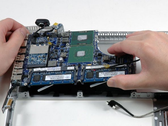
Hold the heat sink with one hand and the fan with your other hand, and lift the heat sink and fan assembly out of the computer. The fan is attached to the heat sink only with a strip of black felt tape, so be sure to remove both parts as a unit.
-
-
-
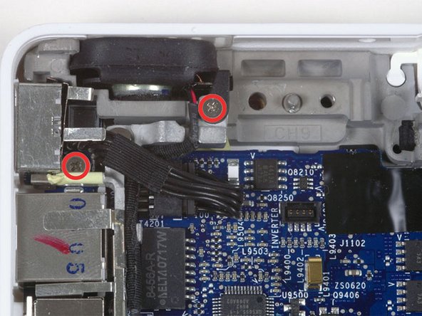
Remove the two Phillips screws securing the MagSafe board and the left speaker to the lower case.
-
-
-
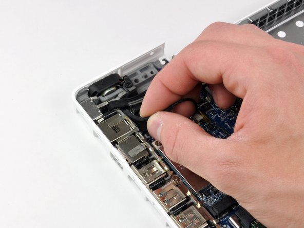
Use a spudger to lift the left speaker out of its housing. Grasp it with your fingers and set it aside.
-
-
-
Use your left hand to move the MagSafe board cables enough to uncover the screw at the top end of the left I/O frame.
-
Remove the 7.5 mm Phillips screw from the top end of the left I/O frame.
-
-
-
Remove the following 2 screws:
-
One 7.5 mm Phillips from the bottom end of the left I/O frame.
-
One 9 mm Phillips from the middle of the left I/O frame.
-
-
-
Lift the left I/O frame up and out of the computer. Pay attention to the thin metal EMI fingers, as they may catch as you remove the left I/O frame.
-
-
-
The MagSafe board is now free of all connections and can be deteached freely from the logic board.
-
Using your fingers, pull out the MagSafe board.
-
-
-
Use a spudger to disconnect the right speaker connector and Bluetooth connector from the logic board.
-
-
-
Lift the logic board up from the right side, and slide it up and out of the computer. Be careful that the right speaker, MagSafe board, and battery connector don't catch on the lower case.
-
-
-
Pry the Bluetooth board up from the lower case.
-
Lift the subwoofer, right speaker, Bluetooth board, and attached cables out of the computer.
-
-
-
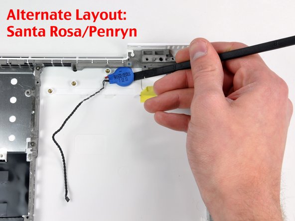
On Santa Rosa/Penryn models, use a spudger to pry up the PRAM battery and remove it from the lower case.
-
-
-
Carefully lift the hard drive connector out of the case slightly, and turn it over to reveal the IR sensor connector beneath. Use a spudger to flip up the tiny bar holding the cable in place.
-
Slide the orange IR sensor cable out of its connector, and lift the hard drive connector out of the computer.
-


To reassemble your device, follow these instructions in reverse order.
To reassemble your device, follow these instructions in reverse order.
