
Introduction
Use this guide to replace a broken iSight camera.
What you need
-
-
Use a coin to rotate the battery-locking screw 90 degrees clockwise.
-
-
-
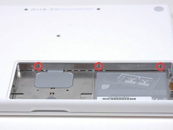
Unscrew the three evenly-spaced Phillips screws from along the rear wall of the battery compartment.
-
-
-
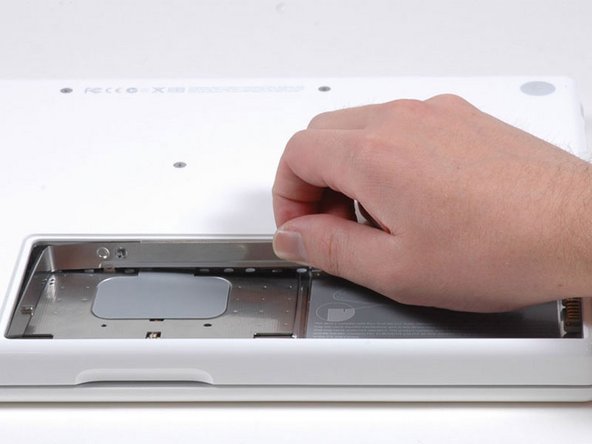
Rotate the L-shaped memory cover so it clears the battery compartment opening and lift it up and out of the computer.
-
-
-
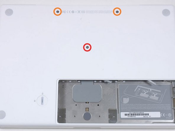
Remove the following 3 screws:
-
One 11 mm Phillips#00 in the middle of the case. (Head: 5mm dia. x .75mm thick)
-
Two 14.5 mm Phillips #00 (Head: 5mm dia. x .75mm thick)
-
-
-
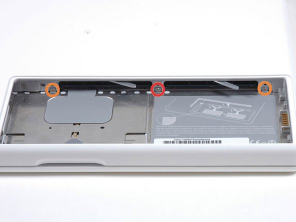
Remove the following 3 screws from the rear wall of the battery compartment:
-
One 3 mm Phillips #0. (Head: 2.75 mm. dia.)
-
Two 4 mm Phillips #0 on the either side. (Head: 2.75mm dia.)
-
-
-
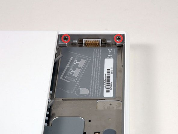
Remove the two Phillips screws from either side of the right wall of the battery compartment (not the ones closest to the battery connector).
-
Two 6.25 mm Phillips #000. (Head: 4 mm. dia. x .5mm thick)
-
-
-
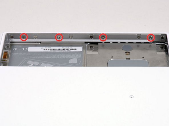
Remove the four indicated Phillips screws from the front wall of the battery compartment. When working from the left, remove the 2nd, 4th, 7th and 9th screw.
-
Four 3.25 mm Phillips #000. (Head: 4 mm. dia. x 4mm thick)
-
-
-
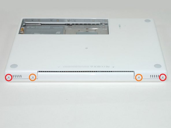
Remove the following 4 screws from the back of the computer:
-
The longer screws go on the inside, shorter screws on the outside.
-
Two 11 mm Phillips #00, with Shank (2.2mm dia. x 2 mm len.) (Head: 3.2 mm. dia. x .5mm thick)
-
Two 7.25 mm Phillips #00, with Shank (2mm dia. x 3.75 mm len.) (Head: 3.2 mm. dia. x .5mm thick)
-
-
-
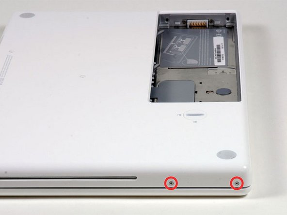
Remove the two Phillips screws from the optical drive side of the computer.
-
Two 5.2 mm Phillips #00, with Shank (2.3mm dia. x 3.5 mm len.) (Head: 3.2 mm. dia. x .5mm thick)
-
-
-
Starting near the display and working around to the front of the computer, pry up on the upper case. A or a medium hard guitar pick may help you to do this.
-
-
-
While holding up the upper case, pull up the black tab of the silver cable away from its connector.
-
While you have the upper case removed, you may want to take the opportunity to remove dust, hair, etc. It's best to use a can of compressed air, though if you use a brush, make sure that its bristles are made of a material (usually animal hair) that doesn't generate static electricity, which can destroy electronics.
-
-
-
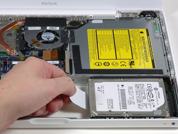
Grasp the white plastic tab attached to the hard drive and pull it to the left, removing the hard drive from the computer.
-
-
-
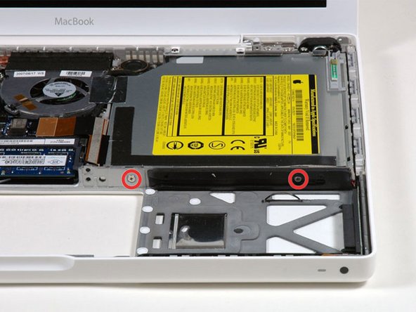
Remove the two Phillips screws from the front edge of the optical drive.
-
Two 3.25 mm Phillips #000, (Head: 4 mm. dia. x .3 mm thick)
-
-
-
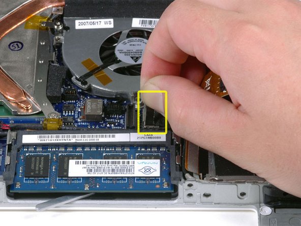
Disconnect the orange optical drive ribbon cable from the logic board. This cable can also be disconnected by prying straight up using a spudger.
-
-
-
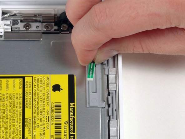
Disconnect the newly revealed display data cable. If there is no pull-tab on the top of the connector, it may be helpful to use a spudger to disconnect this connector.
-
-
-
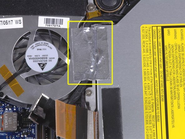
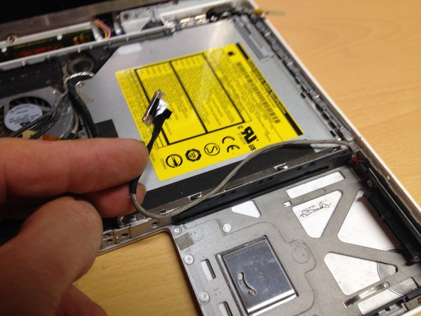
Peel up the foil tape between the fan and the optical drive. Lift the foil tape from the fan side, leaving it attached to the optical drive.
-
During reassembly, be sure to route the cables beneath the tape before reattaching it.
-
-
-
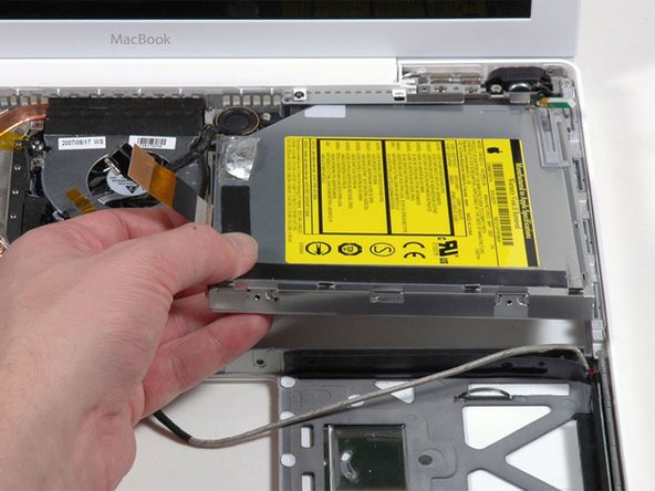
Pull up the display data cable from along the edge of the optical drive to reveal a silver Phillips screw.
-
-
-
Remove the 2 mm Phillips #00 screw securing the optical drive.
-
The Bluetooth cable may be covering the screw. If so, carefully push it aside. You may need to unscrew the cable clip to free the cable enough.
-
-
-
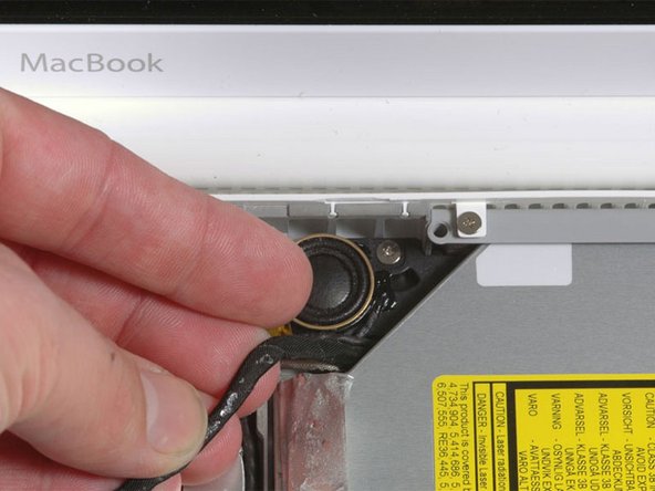
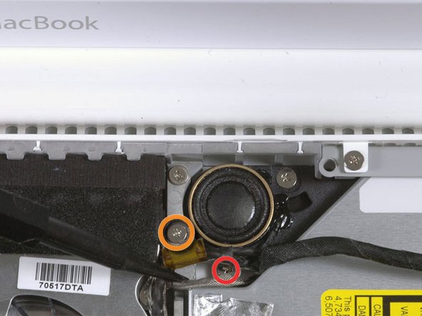
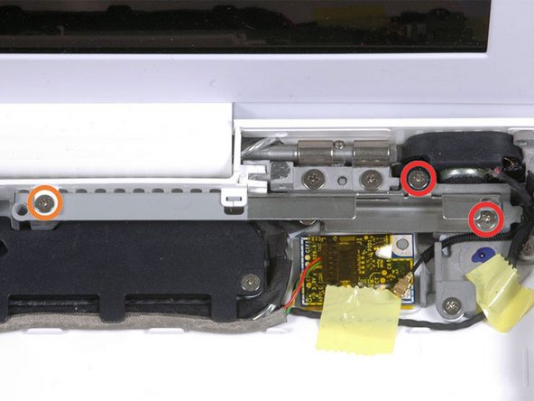
Remove the following 3 screws:
-
Two 3 mm Phillips near the right speaker.
-
One 6 mm Phillips threaded through a hole in a plastic finger above the subwoofer.
-
-
-
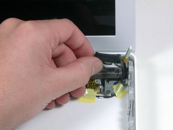
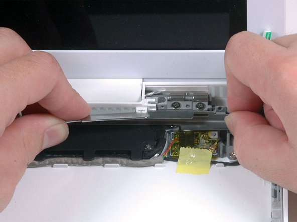
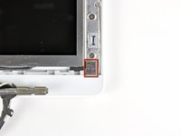
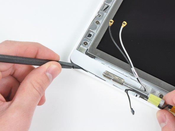
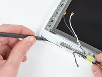
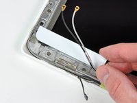
Using a spudger, gently pry up the white plastic slot and slide the metal c-channel to the right and away from the display.
-
-
-
Use a spudger to carefully disconnect the microphone cable from the logic board. You'll want to work from side to side, and slowly wiggle the connector out of its socket.
-
-
-
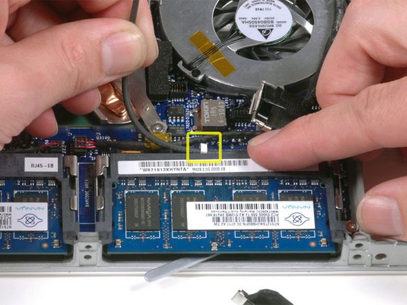
Lift up on the black right speaker cable with one hand, and deroute the microphone cable from the silver metal clip just above the right RAM slot.
-
-
-
If you didn't remove the ground loop screw in step 20 above, remove it now. It's a 7 mm (may be 4.2 mm in Santa Rosa/Penryn models) Phillips screw securing the ground loop in the right speaker cable and microphone cable to the metal framework.
-
-
-
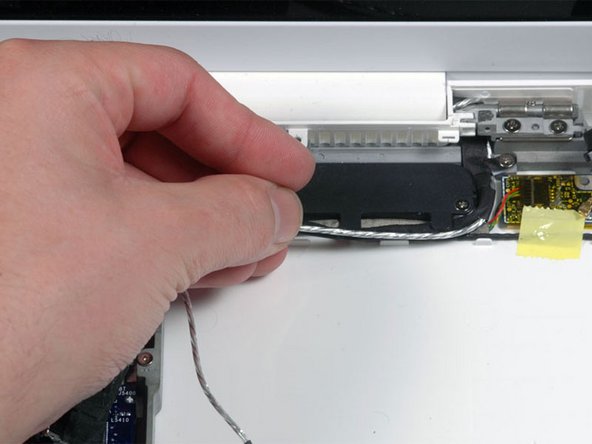
Deroute the microphone cable and the black display data cable from the tabs at the bottom of the subwoofer.
-
-
-
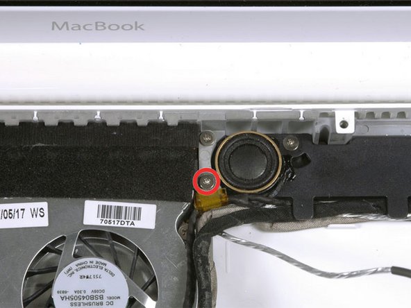
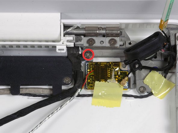
Remove the single 3 mm Phillips screw securing the ground loop in the display data cable located just above the Bluetooth board.
-
-
-
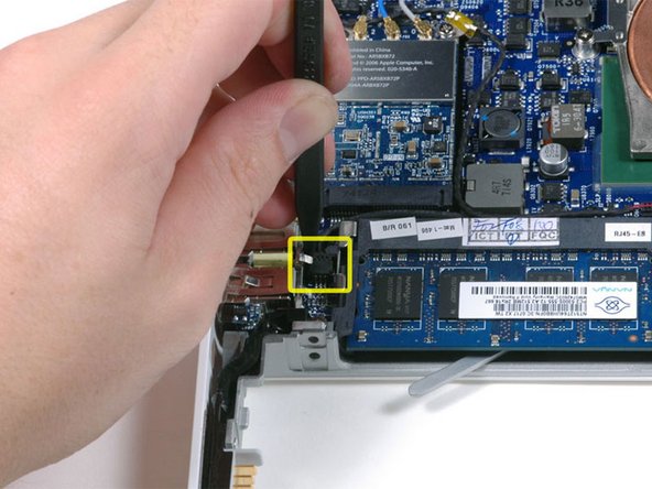
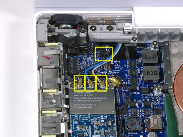
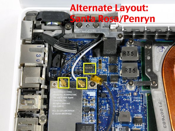
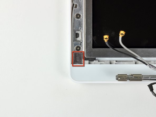
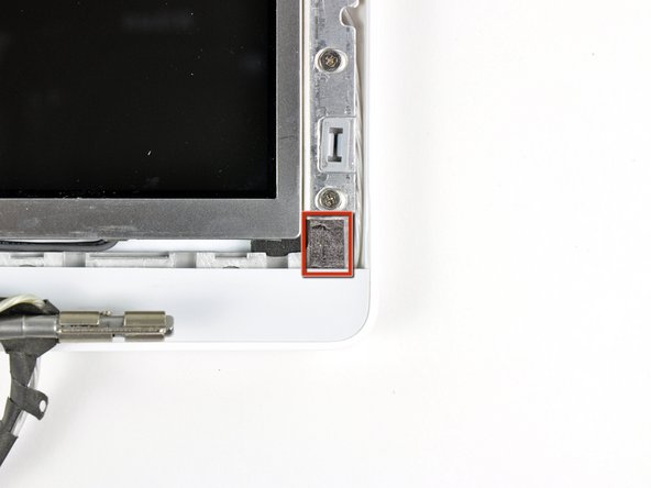
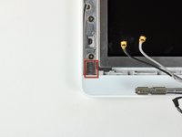
Disconnect the three antenna cables from the Airport card. There may be a square foam piece over the logic board connector.
-
-
-
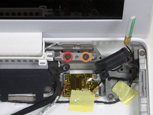
Remove the following 2 screws from the right hinge mount:
-
One 6 mm Phillips on the left side of the hinge mount.
-
One 10 mm Phillips on the right side of the hinge mount.
-
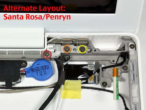
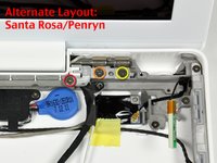
For Santa Rosa/Penryn models, see second picture and remove:
-
One 3 mm smalller diameter Phillips on the far left.
-
One 5.2 mm larger diameter 4.2 mm head Phillips in the middle.
-
One 10 mm Phillips from the far right.
-
Lift the right hinge mount with the small plastic piece out of the computer.
-
-
-
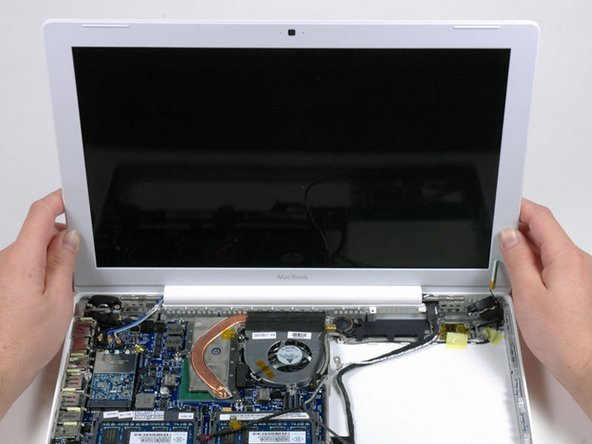
Hold the display with one hand while removing the screws from the left hinge mount.
-
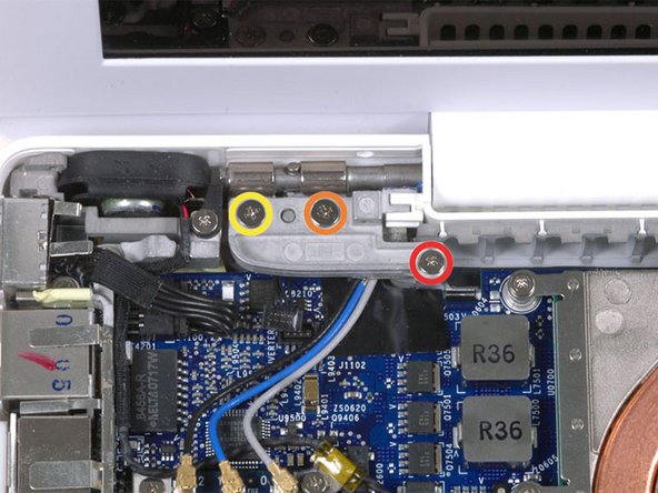
Remove the following 3 screws from the left hinge mount:
-
One 7.2 mm smaller diameter Phillips from the right side.
-
One 5.2 mm larger diameter Phillips from the middle.
-
One 10 mm Phillips from the left side.
-
Lift the left hinge mount with plastic piece out of the computer.
-
Check that the cables on the right are not trapped under other cables.
-
-
-
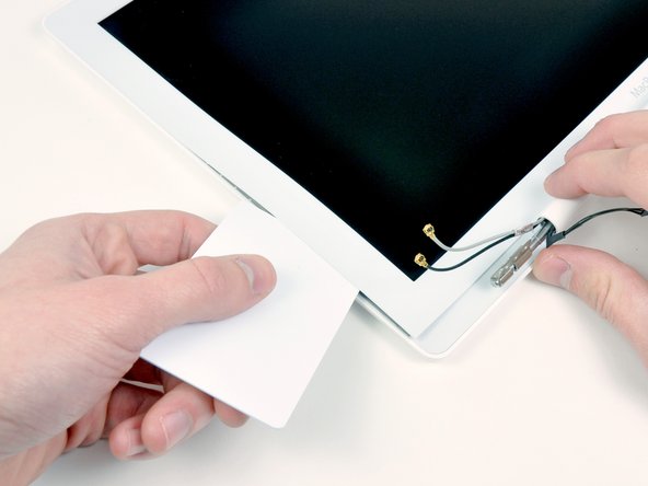
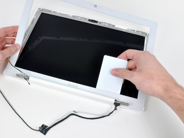
Use a thin plastic card to release the tabs holding the front display bezel to the display assembly. There are five tabs along the left side of the display bezel.
-
-
-
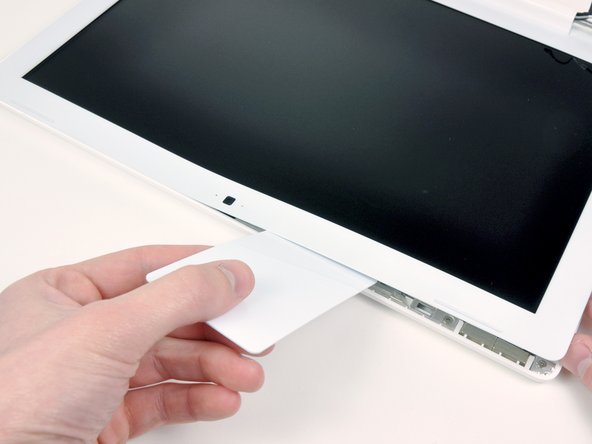
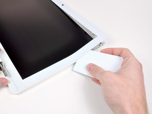
Lift up the front display bezel from the top and use your plastic card to free the tabs along the bottom edge of the display bezel.
-
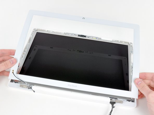
After freeing all holding tabs, lift the front display bezel away from the display assembly.
-
-
-
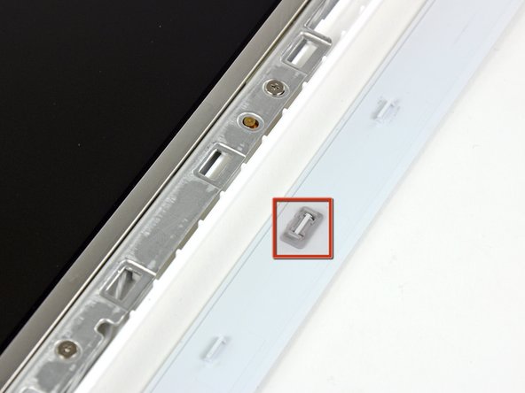
Use a metal spudger or another thin tool to carefully pry the gray plastic clips off the tabs molded into the front display bezel. A 0.8mm flat screwdriver may be useful for this step.
-
-
-
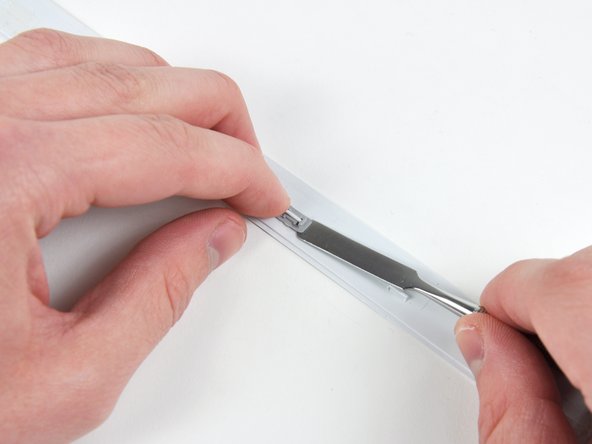
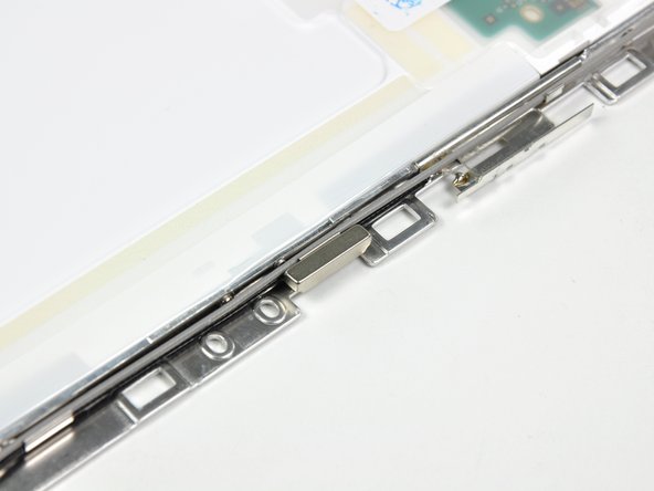
Insert the longer end of the retaining clip beneath the edge of its recess cut into the LCD bracket.
-
Use the edge of a metal spudger to push the shorter tab on the other side of the retaining clip into the recess cut into the LCD bracket.
-
-
-
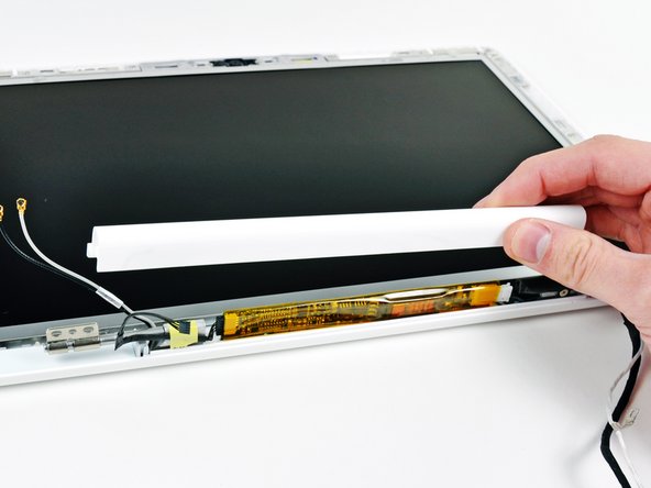
While holding the display down with one hand, use your other hand to lift the clutch cover off the clutch hinges.
-
-
-
Lift up the right side of the clutch cover and guide the display data and iSight cables through the gap in the clutch cover.
-
Lift the clutch cover out of the display assembly.
-
-
-
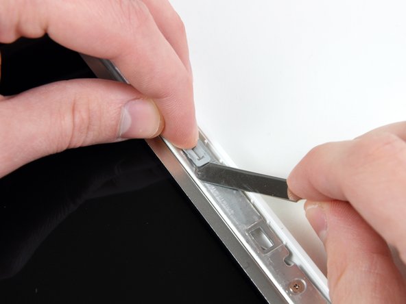
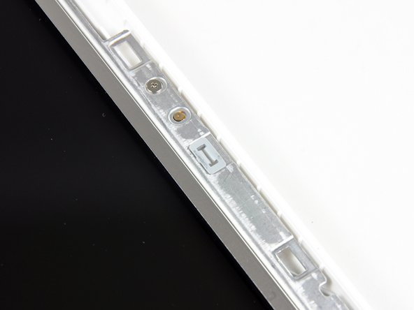
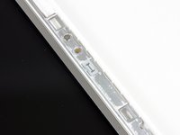
Use a spudger to slide the left bezel cover towards the LCD panel.
-
Lift the left bezel cover off the display assembly.
-
-
-
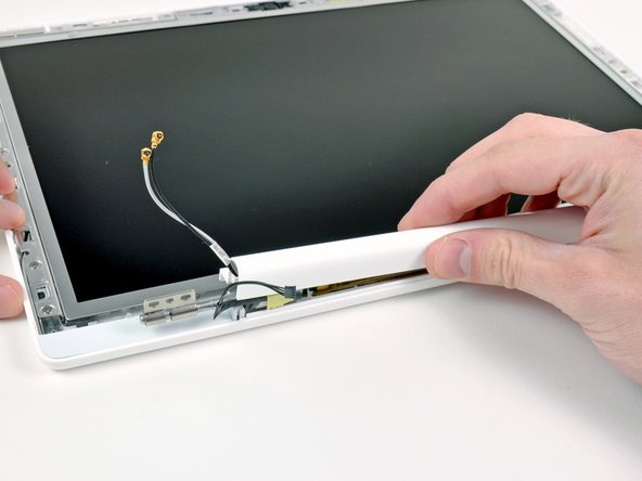
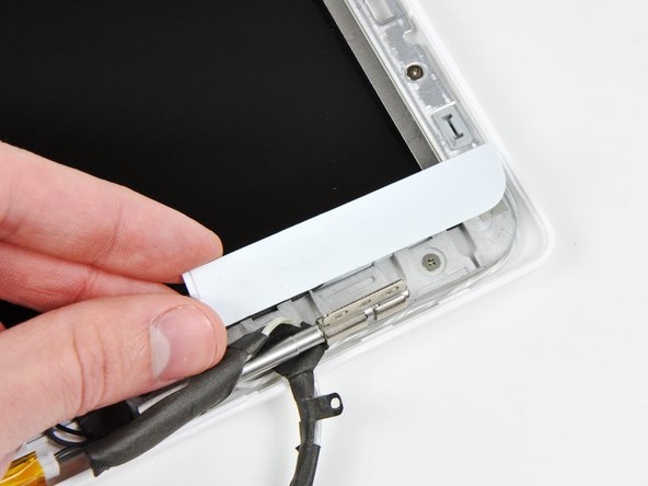
Use a spudger to slide the right bezel cover toward the LCD panel.
-
Lift the right bezel cover off the display assembly.
-
-
-
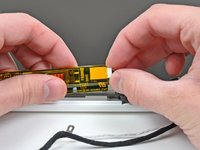
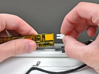
Lift the inverter out of the display slightly and disconnect the backlight cable from its right side.
-
Place the inverter back down in its recess.
-
-
-
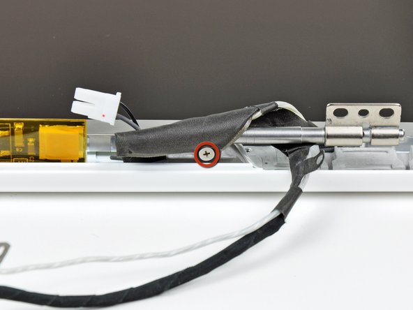
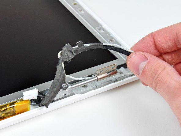
Remove the single 3.2 mm Phillips screw securing the display data cable to the right clutch hinge.
-
-
-
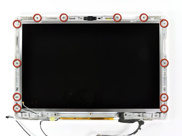
Remove the twelve 4.2 mm Phillips screws securing the LCD assembly to the rear display bezel.
-
-
-
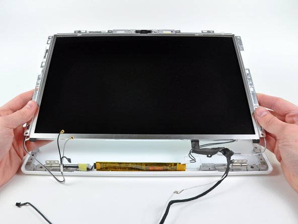
Lift the LCD assembly out of the rear display bezel, minding any cables that may get caught.
-
-
-
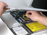
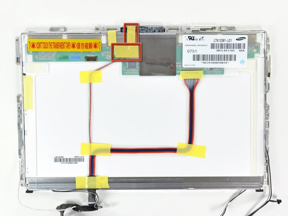
Remove the two pieces of yellow tape covering the camera cable near the top edge of the LCD assembly.
-
-
-
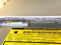
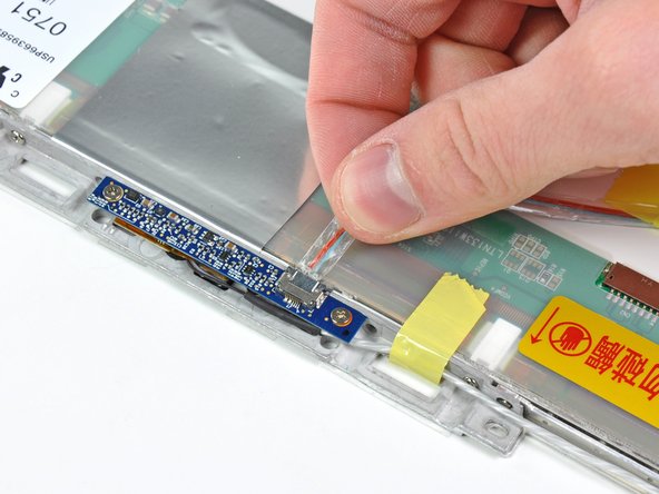
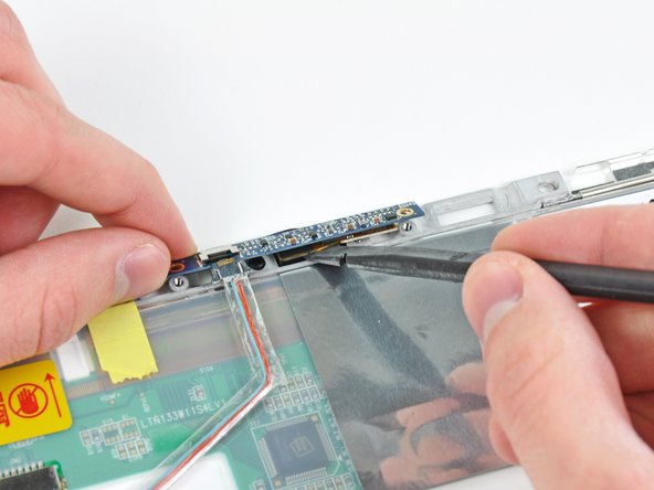
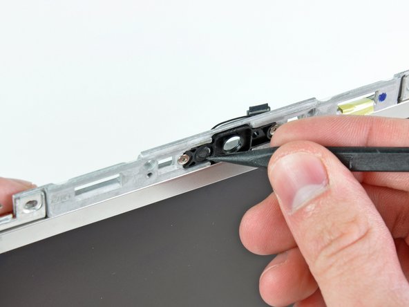
Use the flat end of a spudger to carefully pry the camera out of its recess.
-
Remove the iSight from the LCD assembly.
-
-
-
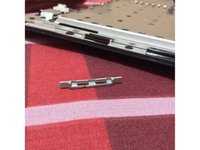
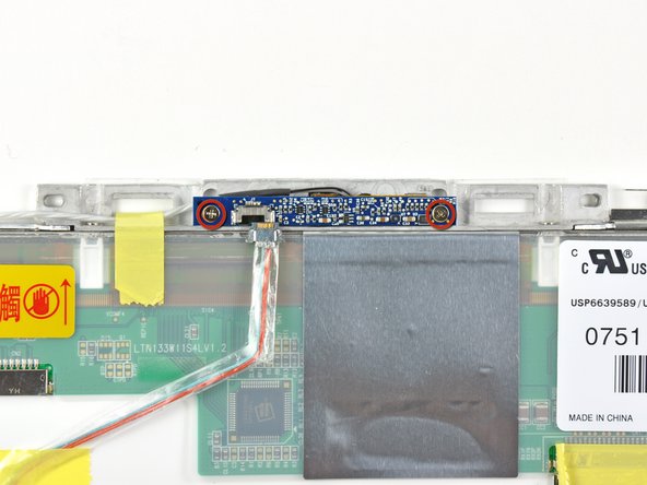
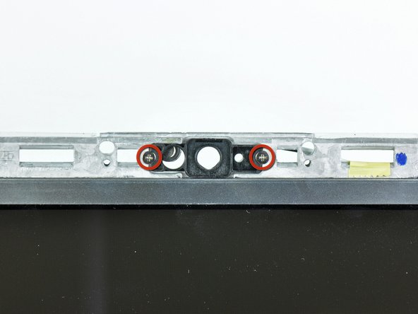
Remove the two 2.2 mm Phillips screws securing the iSight bezel to its bracket.
-
Remove the iSight bezel.
-


To reassemble your device, follow these instructions in reverse order.
