
Introduction
Use this guide to replace the LCD rather than the entire display assembly.
What you need
-
-
Remove the following 10 screws securing the lower case to the MacBook Pro 13" Unibody:
-
Seven 3 mm Phillips screws.
-
Three 13.5 mm Phillips screws.
-
-
-
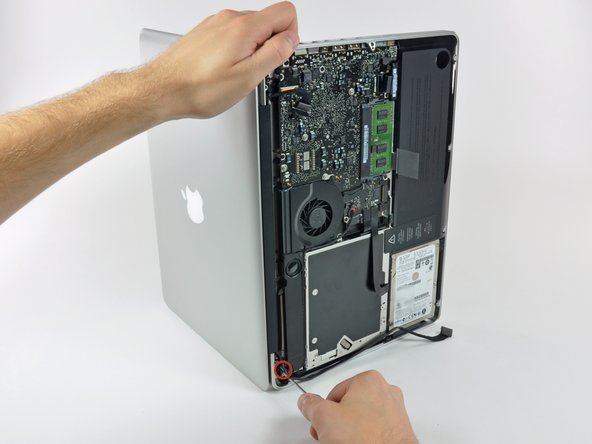
Slightly lift the lower case and push it toward the rear of the computer to free the mounting tabs.
-
-
-
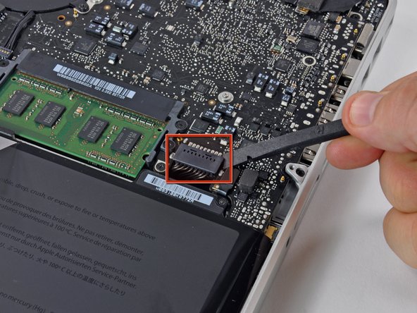
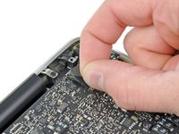
Use the flat end of a spudger to lift the battery connector up out of its socket on the logic board.
-
-
-
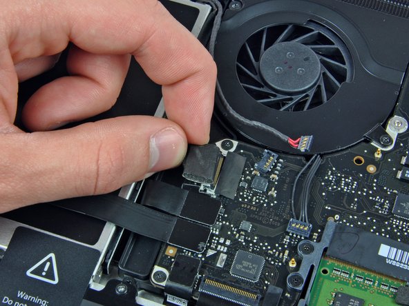
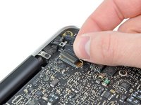
Use the flat end of a spudger to pry up the subwoofer/right speaker cable connector out of its socket on the logic board.
-
-
-
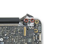
Remove the following screws:
-
Two 10 mm Phillips screws
-
One 3.8 mm Phillips screw
-
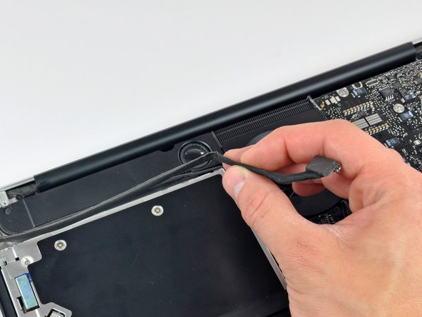
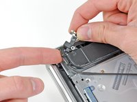
Slide the camera cable bracket out from under the subwoofer and remove it from the computer.
-
-
-
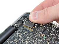
Grab the plastic pull tab secured to the display data cable lock and rotate it toward the DC-In side of the computer.
-
Pull the display data cable connector straight away from its socket.
-
Make sure to pull the connector straight away and not straight up from its socket.
-
-
-
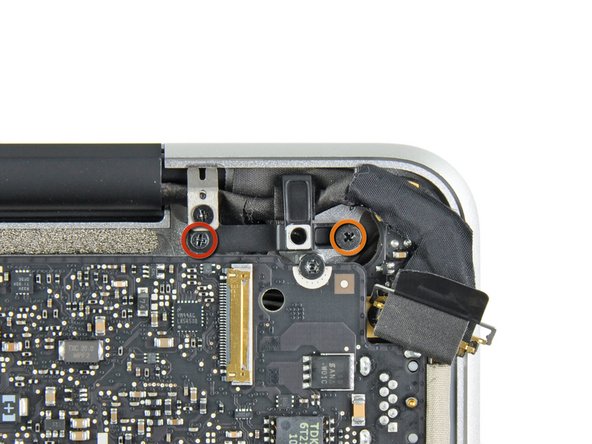
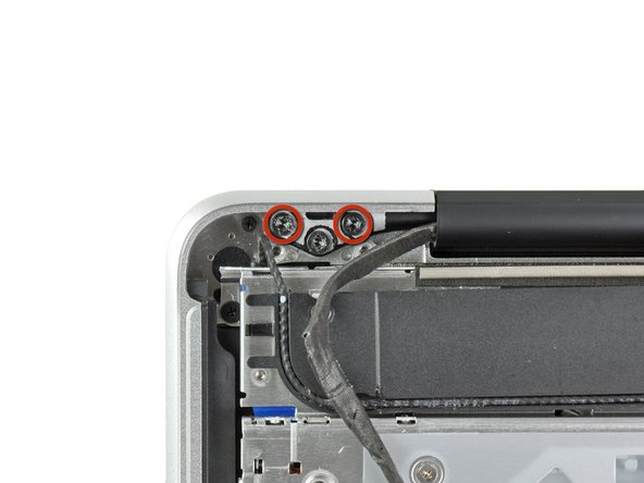
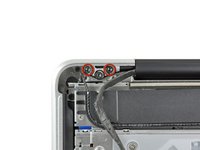
Remove the following two screws securing the display data cable bracket to the upper case:
-
One 8.6 mm Phillips screw
-
One 5.6 mm Phillips screw
-
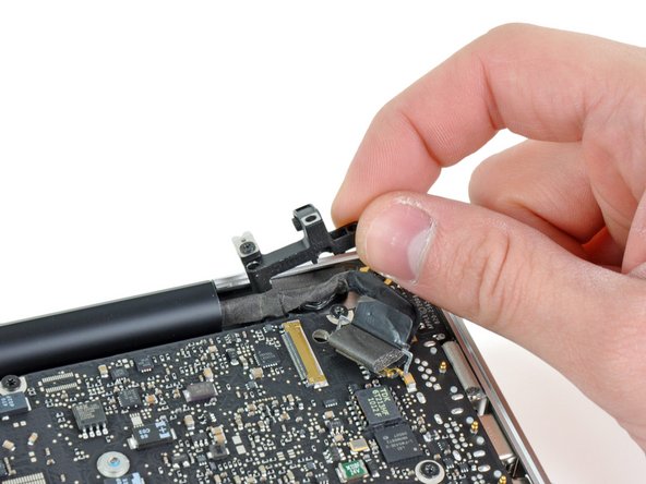
Lift the display data cable bracket out of the upper case.
-
-
-
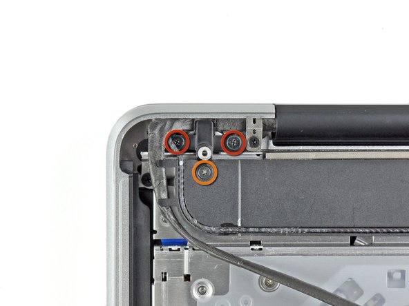
Remove the two outer 6.5 mm T8 Torx screws securing each of the two display brackets to the upper case (4 screws total).
-
-
-
Open your MacBook so the display is perpendicular to the upper case.
-
Place your opened MacBook on a table as pictured.
-
While holding the display and upper case together with your left hand, remove the remaining 6.5 mm T8 Torx screw from the lower display bracket.
-
-
-
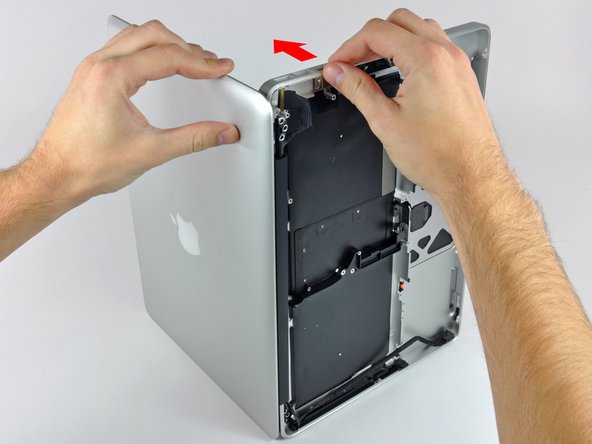
Grab the upper case with your right hand and rotate it slightly toward the top of the display so the upper display bracket clears the edge of the upper case.
-
Rotate the display slightly away from the upper case.
-
-
-
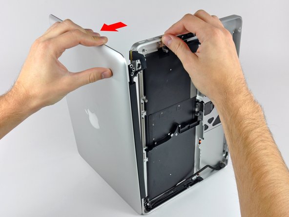
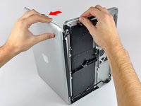
Lift the display up and away from the upper case, minding any brackets or cables that may get caught.
-
-
-
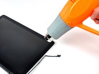
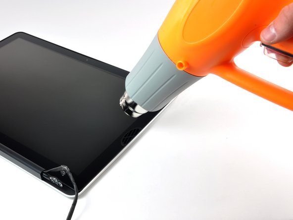
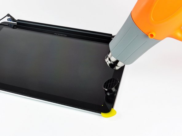
With the heat gun set to low, start by heating the outer black border near the upper right corner of the glass panel.
-
-
-
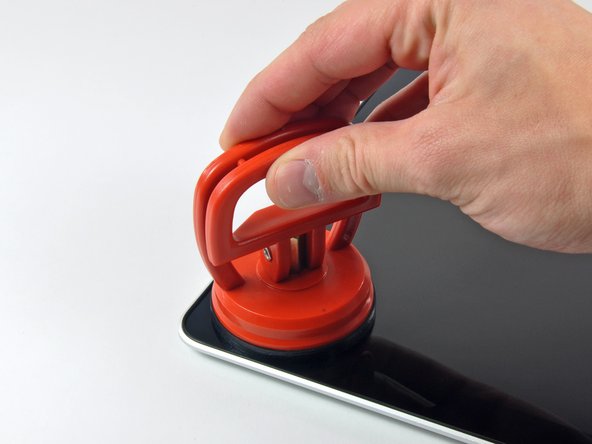
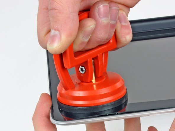
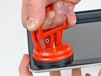
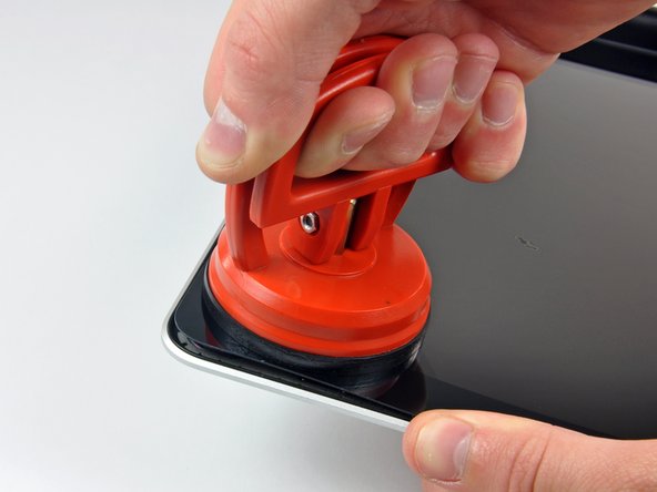
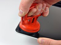
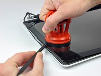
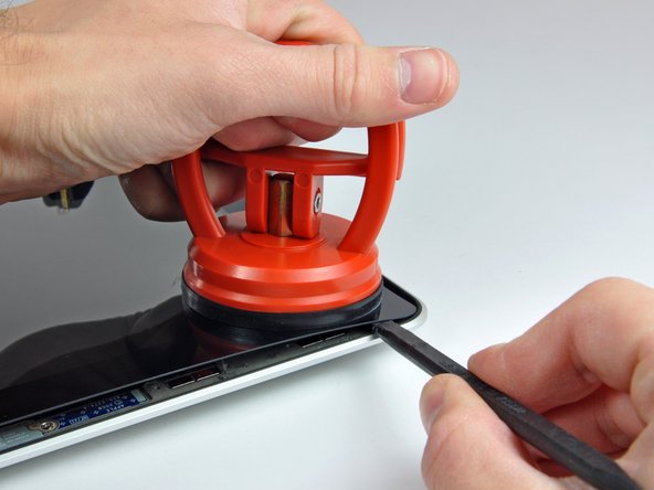
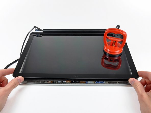
With the panel sufficiently heated, fasten a heavy-duty suction cup near the upper right corner of the display glass.
-
Slowly and gently pull the corner of the display glass up off the display assembly.
-
-
-
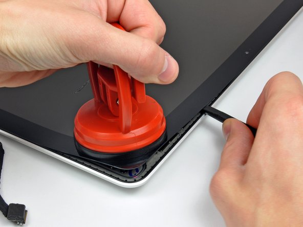
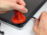
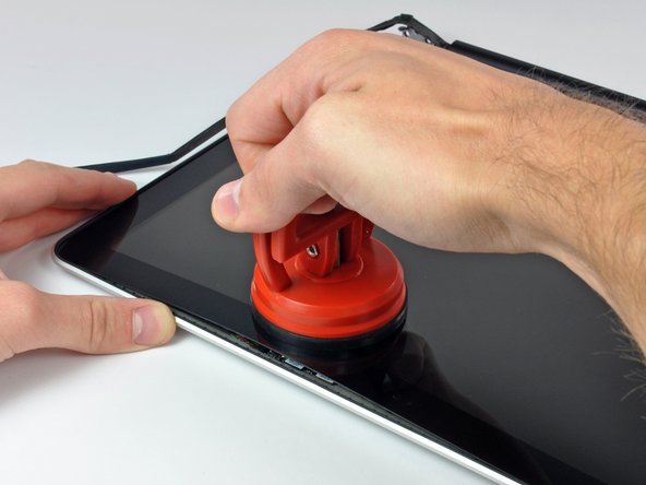
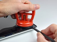
Gently lift the corner of the display glass enough to insert a spudger between it and the display assembly.
-
Use the flat end of a spudger to gently pry up the adhesive securing the front glass to the display.
-
Pry up the glass panel a few inches away from the upper right corner along the top and right edges of the display.
-
-
-
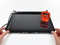
Use a heat gun to soften the adhesive under the black strip along the right side of the front glass panel.
-
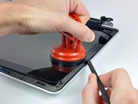
Attach a suction cup along the right side of the front glass panel.
-
Pull up on the glass panel while you use the flat end of a spudger to separate it from the rest of the display assembly.
-
Continue working along the right edge of the front display glass until it is separated from the display.
-
-
-
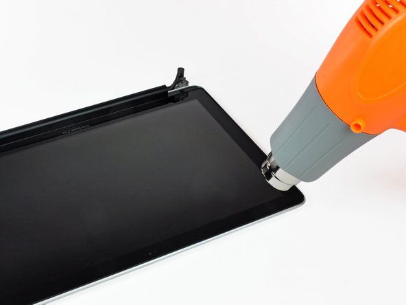
Use your heat gun to soften the adhesive under the black strip along the top edge of the glass display panel.
-
Attach a suction cup near the top edge of the glass display panel and use it to pull the glass panel up off the display.
-
Work along the top edge of the glass panel, carefully using the flat end of a spudger to separate the adhesive if necessary.
-
-
-
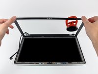
Use a heat gun to soften the adhesive under the black strip near the upper left corner of the glass display panel.
-
Attach a suction cup near the upper left corner of the glass display panel.
-
Pull up on the suction cup and use the flat end of a spudger to carefully pry the glass display panel out of the display assembly.
-
-
-
Use a heat gun to soften the adhesive under the black strip along the left side of the front glass panel.
-
Attach a suction cup along the left side of the front glass panel.
-
Pull up on the glass panel while you use the flat end of a spudger to separate it from the rest of the display assembly.
-
Continue working along the left edge of the front display glass until it is separated from the display.
-
-
-
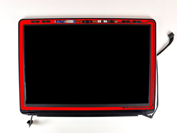
Now that the top, left, and right edges of the glass are free from the display, slowly lift the top edge of the glass panel and gently rotate it out of the display.
-
-
-
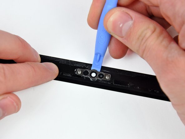
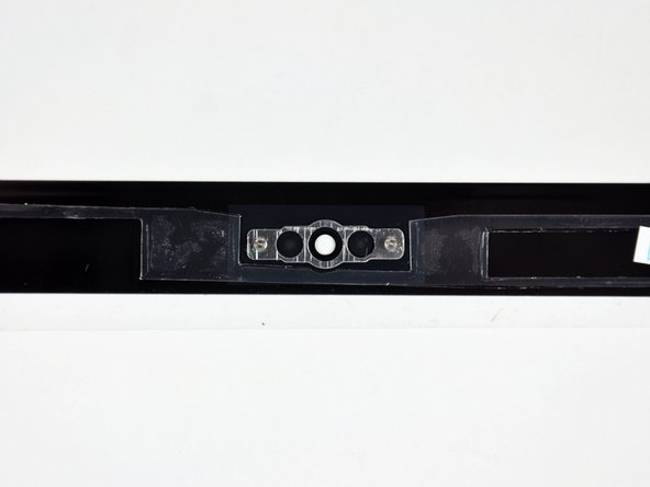
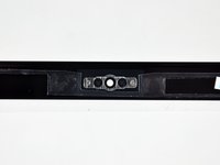
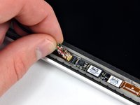
Insert the edge of a plastic opening tool between the display glass and the camera bracket, and run it around the camera bracket to separate it from the display glass.
-
-
-
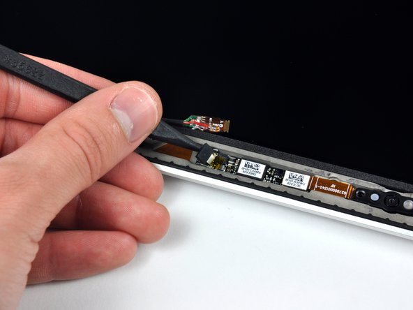
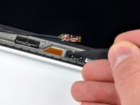
To reconnect the cable, first use the tip of a spudger to remove the piece of foam tape over the camera cable ZIF socket.
-
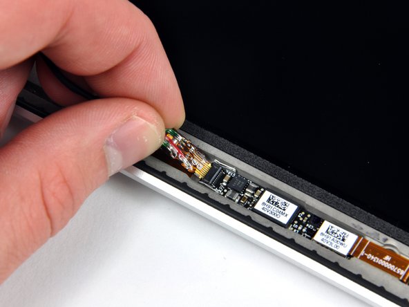
Use the tip of a spudger to flip up the ZIF cable retainer on the camera cable socket.
-
Insert the camera cable into its socket on the camera board and use the tip of a spudger to snap down the ZIF cable retainer, locking the cable in place.
-
-
-
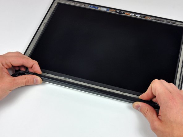
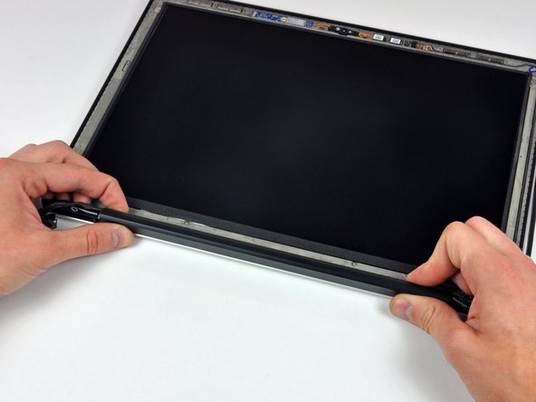
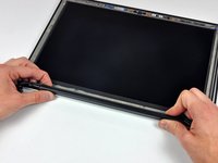
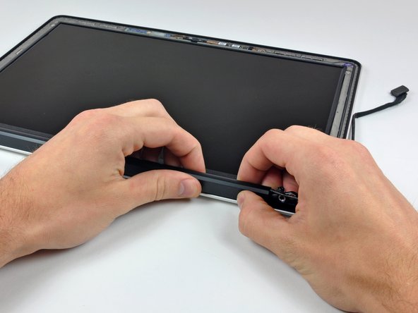
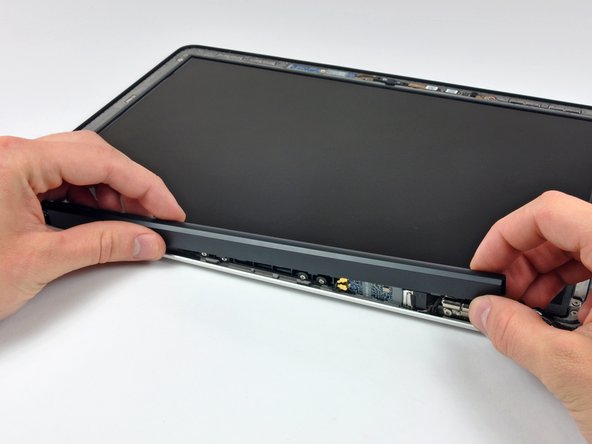
Starting at its far right end, rock the clutch cover along its long axis while pulling it away from the clutch hinge.
-
Working from right to left, carefully continue to release and lift the clutch along the lower edge of the display assembly.
-
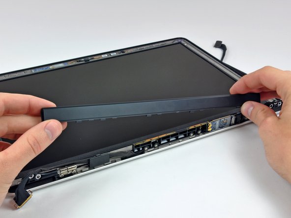
Lift the clutch cover up off the front bezel and set it aside.
-
-
-
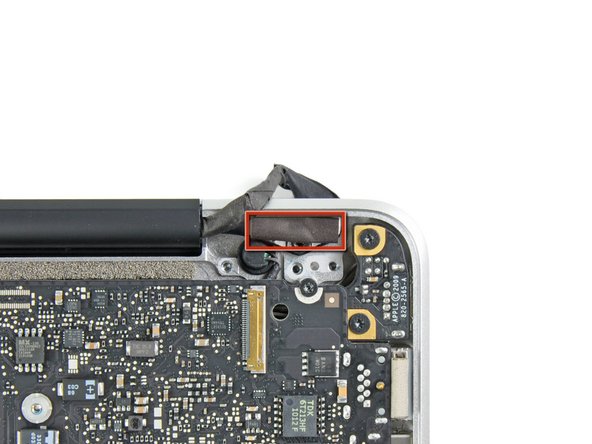
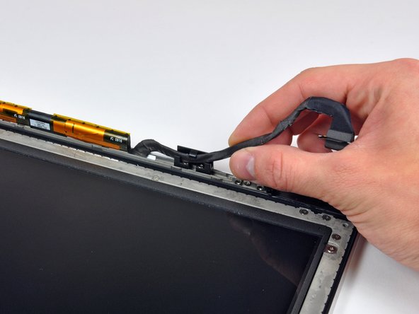
De-route the display data cable from its retaining bracket near the lower left edge of the display.
-
-
-
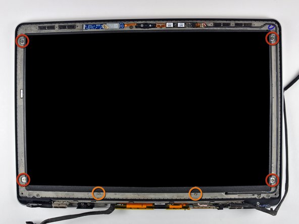
Remove the following six screws securing the LCD panel to the front bezel:
-
Four 3.25 mm Phillips with large heads.
-
Two 3.2 mm Phillips with small heads.
-
-
-
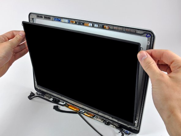
Hold the display vertically and tip it enough to grab the top edge of the LCD and rotate it slightly out of the display assembly, being careful not to break the circuitry off its lower edge.
-
-
-
Pull the LCD toward the top edge of the display to slide the circuitry along its lower edge out of the recess in the aluminum display assembly.
-
-
-
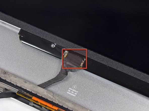
Peel the piece of tape covering the display data cable connector away from the edge closest to the LCD.
-
-
-
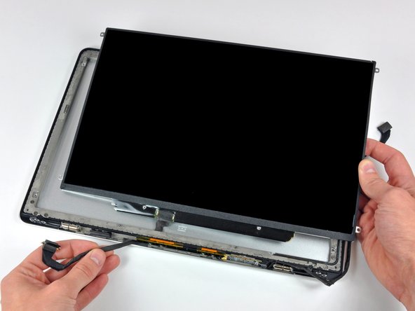
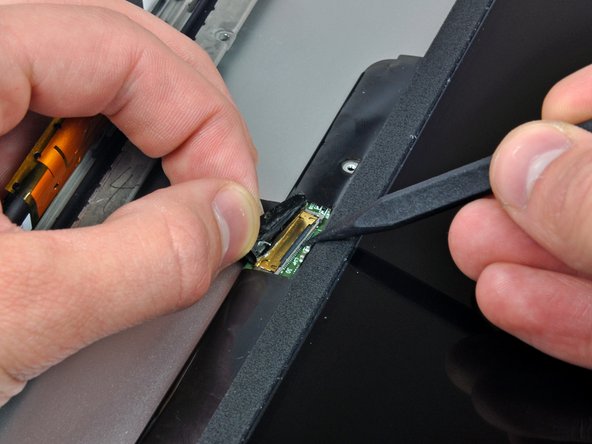
Use the tip of a spudger to flip up the thin steel retaining clip securing the display data cable to its socket on the LCD.
-
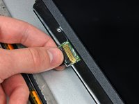
Pull the display data cable straight away from its socket on the LCD.
-
Lift the LCD out of the display assembly and set it aside.
-


To reassemble your device, follow these instructions in reverse order.
