
Introduction
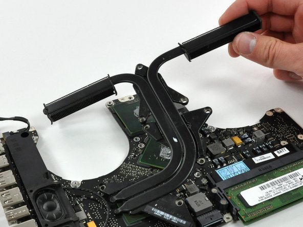
The heat sink helps keep the processor cool and happy. Be sure to replace the thermal paste before reinstalling the heat sink.
What you need
-
-
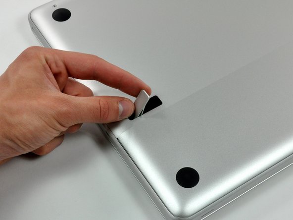
With the case closed, place the Unibody top-side down on a flat surface.
-
Depress the grooved side of the access door release latch enough to grab the free end. Lift the release latch until it is vertical.
-
-
-
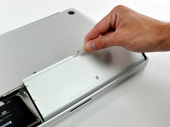
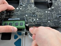
Grab the translucent plastic tab and pull the battery up and out of the Unibody.
-
If the latch is depressed it will lock the battery in place.
-
-
-
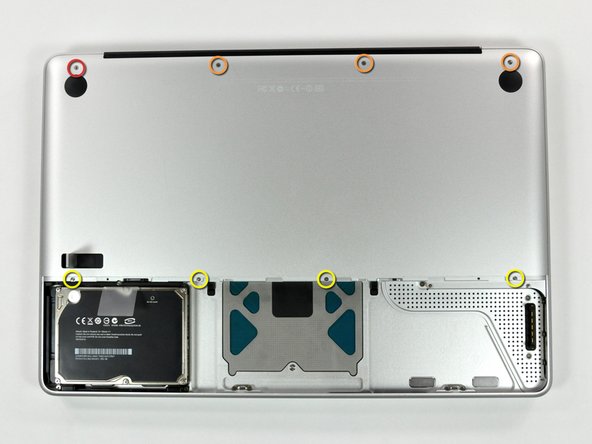
Remove the following eight screws securing the lower case to the chassis:
-
One 5.4 mm Phillips screw.
-
Three 14 mm Phillips screws.
-
Four 3.5 mm Phillips screws.
-
-
-
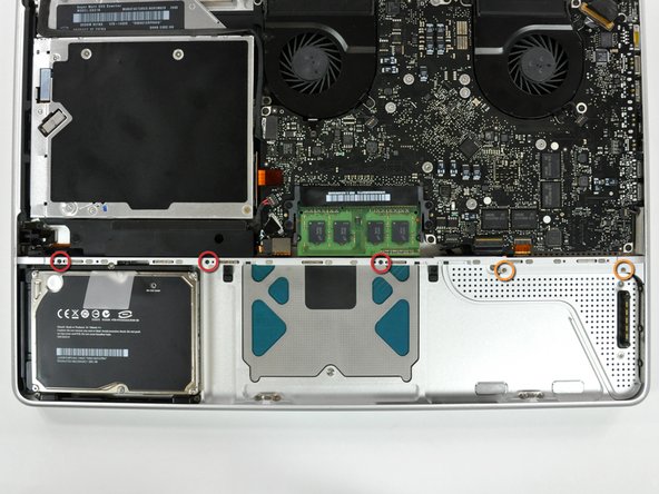
Remove the following 5 screws securing the mid wall to the upper case:
-
Three 10.5 mm Phillips screws.
-
Two 3.7 mm Phillips screws.
-
-
-
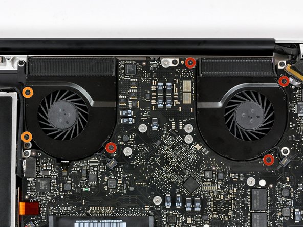
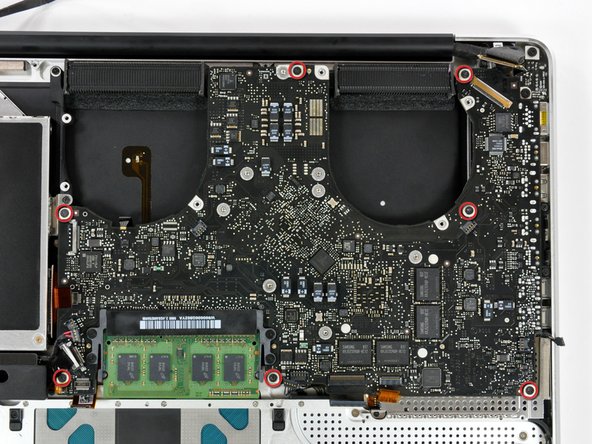
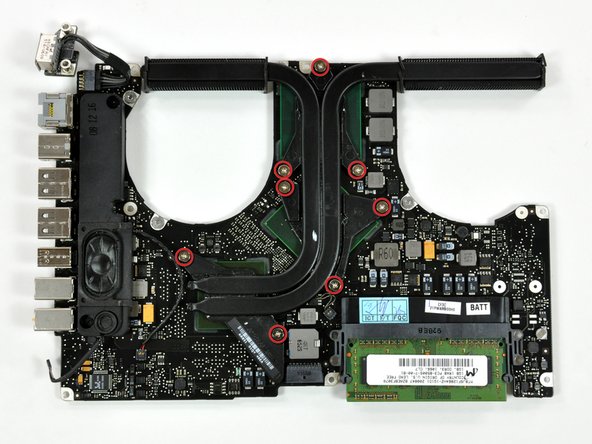
Remove the following six screws securing both the right fan and the left fan to the logic board:
-
Four 3.5 mm Phillips screws.
-
Two 3.2 mm Phillips screws.
-
-
-
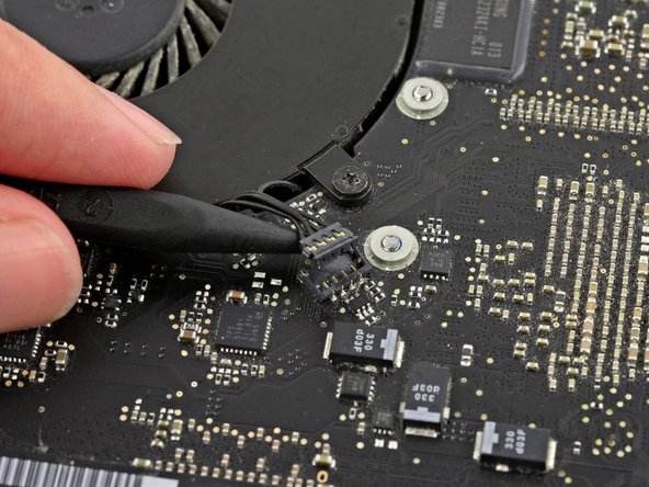
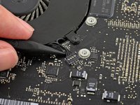
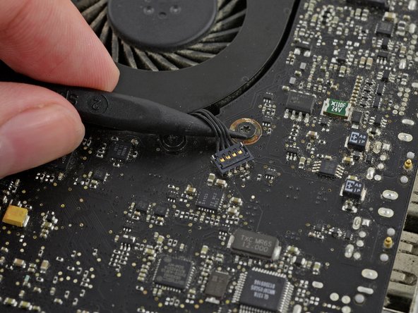
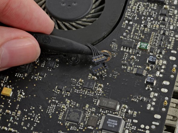
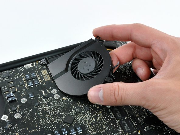
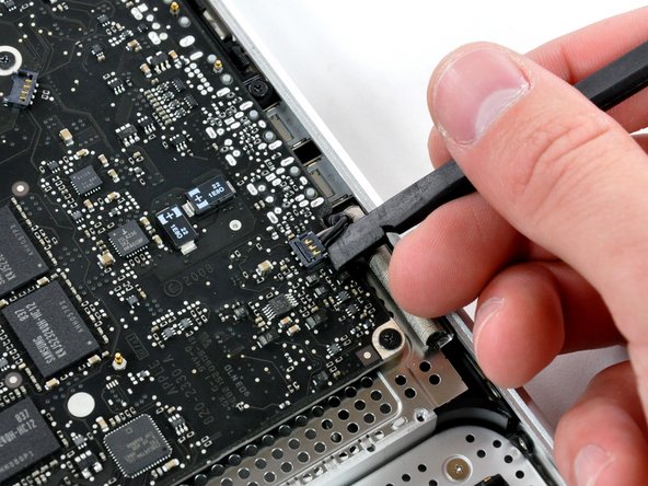
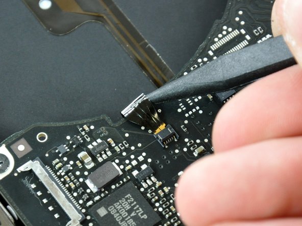
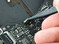
Use the tip of a spudger to lift the right fan connector straight up from its socket on the logic board.
-
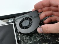
Remove the right fan from the case.
-
-
-
Use the tip of a spudger to lift the left fan connector straight up from its socket on the logic board.
-
Remove the left fan from the case.
-
-
-
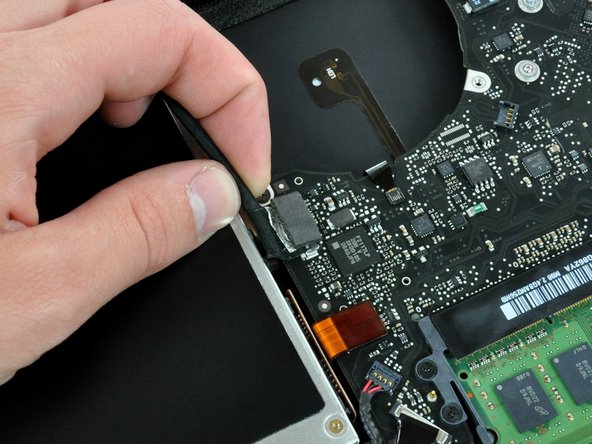
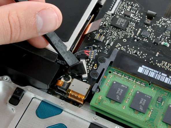
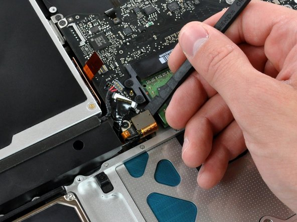
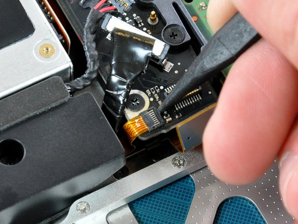
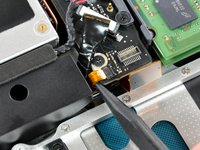
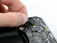
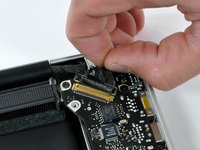
Remove any adhesive from the camera cable connector.
-
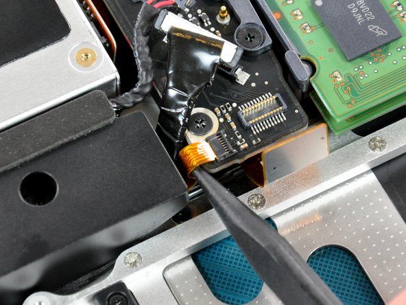
Disconnect the camera cable by pulling the male end out of its socket, parallel to the logic board, do not lift it upwards.
-
-
-
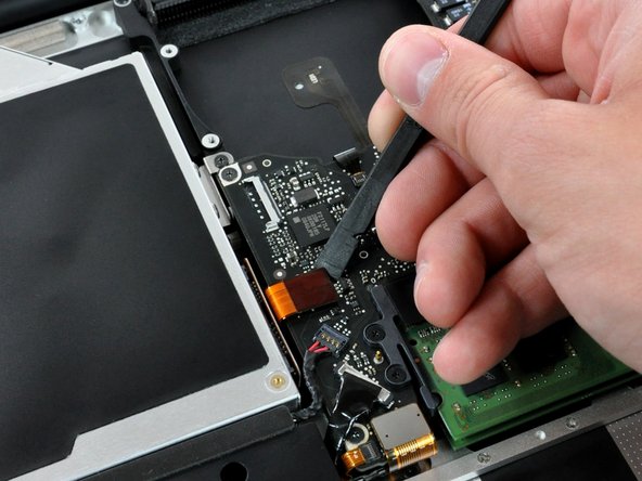
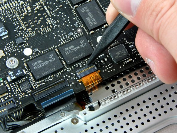
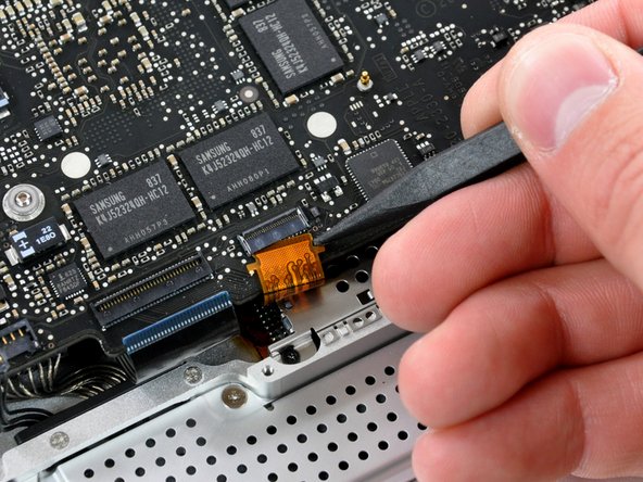
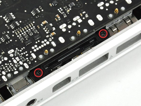
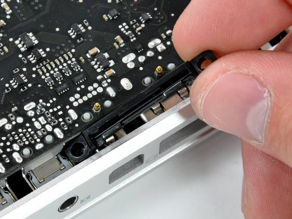
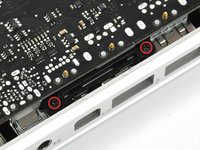
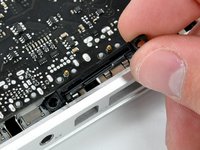
Use a spudger to carefully pry the optical drive connector straight up off its socket on the logic board.
-
-
-
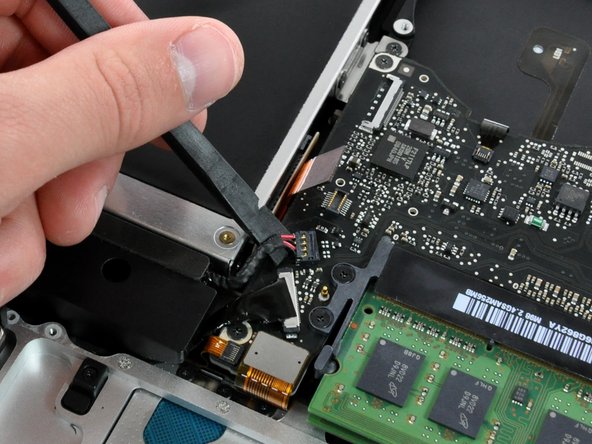
Using the flat end of a spudger, pry the subwoofer connector straight up off its socket on the logic board.
-
-
-
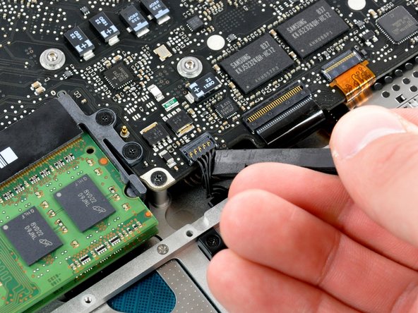
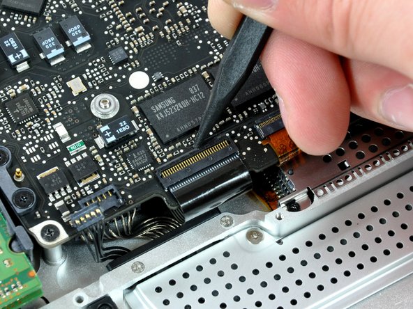
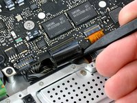
Use the flat end of a spudger to pry the silver-colored hard drive cable connector straight up out of its socket on the logic board.
-
-
-
Use a spudger to pry the trackpad connector straight up out of its socket on the logic board.
-
-
-
Using the tip of a spudger, flip up the IR/sleep LED ribbon cable retaining flap.
-
Pull the IR/sleep LED ribbon cable straight out of its socket.
-
-
-
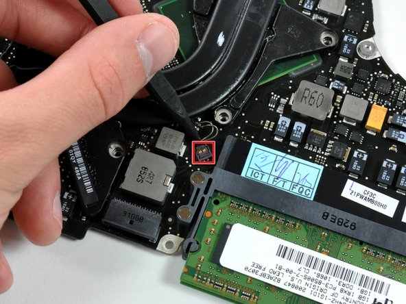
Use a spudger to pry the battery indicator light connector straight up out of its socket on the logic board.
-
-
-
Using the tip of a spudger, flip up the keyboard ribbon cable retaining flap.
-
Pull the keyboard ribbon cable straight out of its socket.
-
-
-
Using the tip of a spudger, flip up the express card cage ribbon cable retaining flap.
-
Pull the express card cage ribbon cable straight out of its socket.
-
-
-
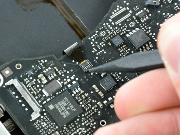
Using the flat end of a spudger, pry the microphone cable connector straight up out of its socket on the logic board.
-
-
-
Grab the plastic pull tab secured to the display data cable lock and rotate it toward the DC-in side of the computer.
-
Pull the display data cable connector straight away from its socket.
-
-
-
Locate the keyboard backlight ribbon cable (near the left fan space).
-
Using the tip of a spudger, flip up the keyboard backlight ribbon cable retaining flap.
-
Pull the keyboard backlight ribbon cable straight out of its socket.
-
-
-
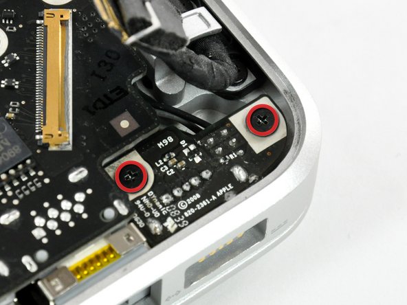
Remove two 3.5 mm Phillips screws securing the bottom case clip to the upper case.
-
Lift the bottom case clip out of the upper case.
-
-
-
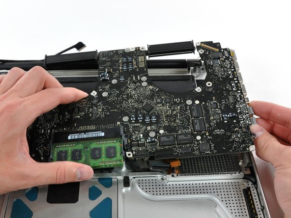
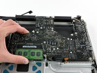
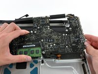
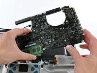
Carefully lift the logic board assembly from the left side and work it out of the upper case, minding the port side that may get caught during removal.
-
-
-
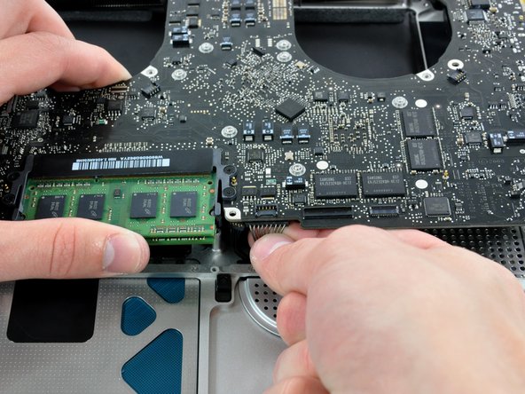
Lift the logic board enough to grab the battery connector and pull it straight away from its socket on the logic board.
-
Lift the logic board assembly out of the upper case.
-


To reassemble your device, follow these instructions in reverse order.
