
Introduction
Replacing the upper case requires the removal of nearly all the components found within your MacBook Pro.
What you need
-
-
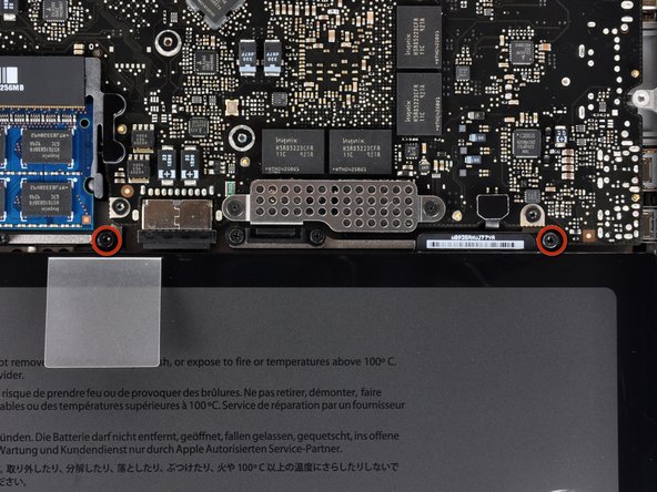
Remove the following ten screws securing the lower case to the upper case:
-
Seven 3 mm Phillips screws.
-
Three 13.5 mm Phillips screws.
-
-
-
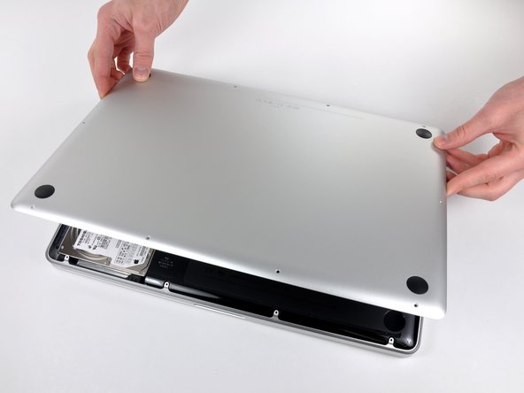
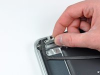
Using both hands, lift the lower case near the vent to pop it off two clips securing it to the upper case.
-
Remove the lower case and set it aside.
-
-
-
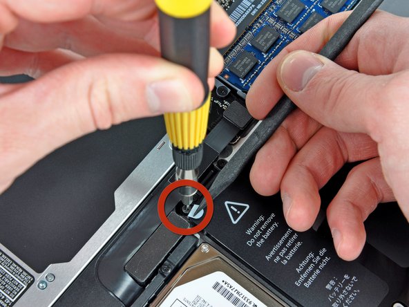
Use the tip of a spudger to bend back the finger of the "Warning: Do not remove the battery" sticker while you remove third five-point Pentalobe screw hidden underneath.
-
-
-
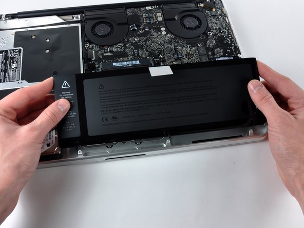
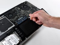
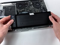
Lift the battery by its plastic pull tab and slide it away from the long edge of the upper case.
-
-
-
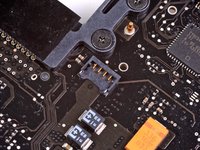
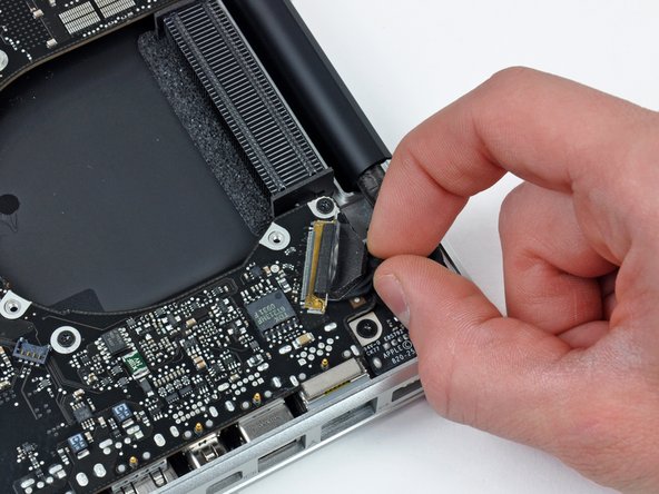
Tilt the battery back enough to access the battery cable connector.
-
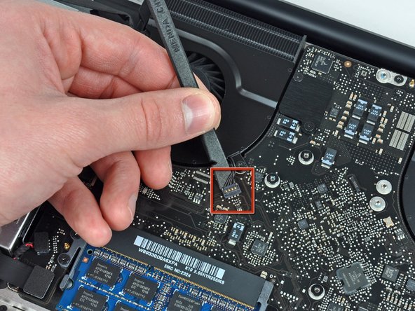
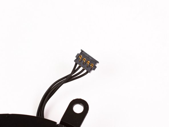
Pull the battery cable connector away from its socket on the logic board and remove the battery from the upper case.
-
-
-
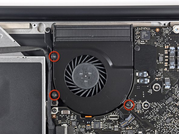
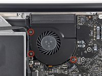
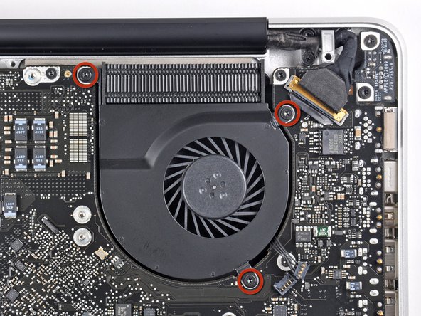
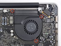
Remove the three T6 Torx screws securing the left fan to the logic board.
-
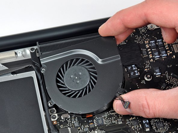
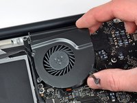
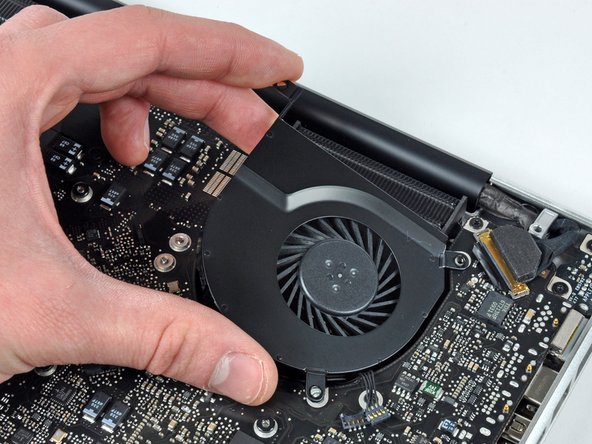
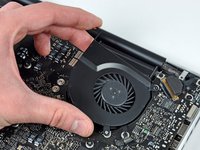
Lift the fan out of the upper case.
-
-
-
Remove the three T6 Torx screws securing the left fan to the logic board.
-
Lift the left fan out of the upper case.
-
-
-
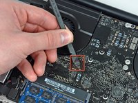
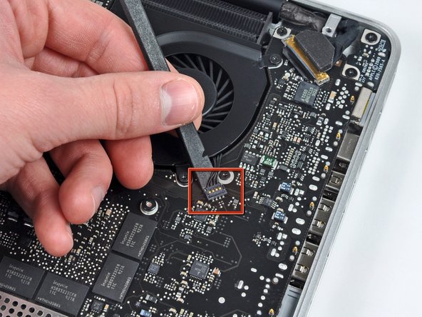
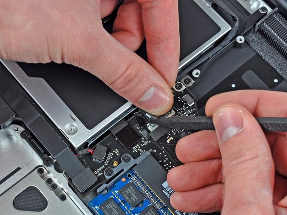
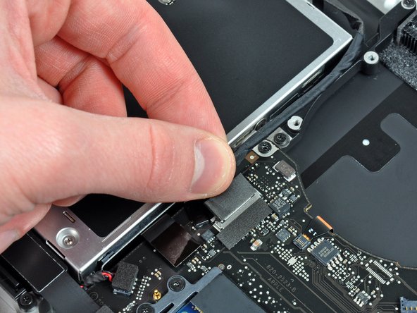
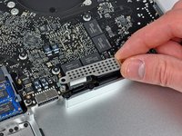
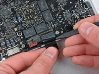
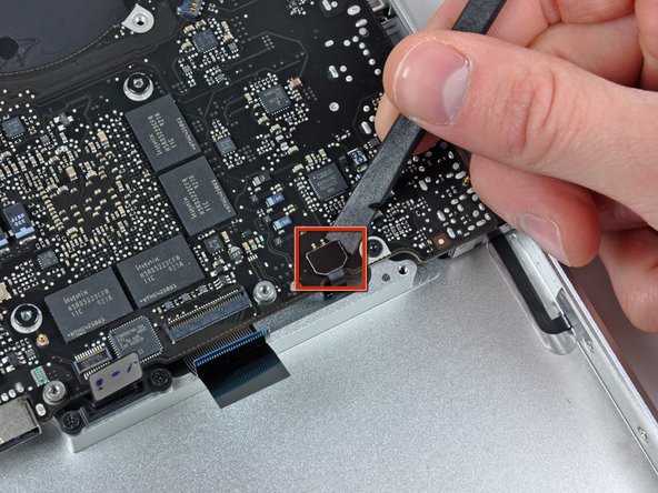
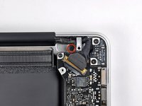
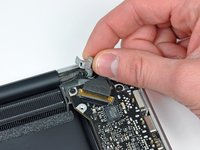
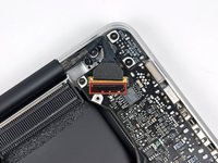
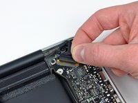
Hold the end of the cable retainer down with one finger while you use the tip of a spudger to slightly lift the other end and rotate it away from the camera cable connector.
-
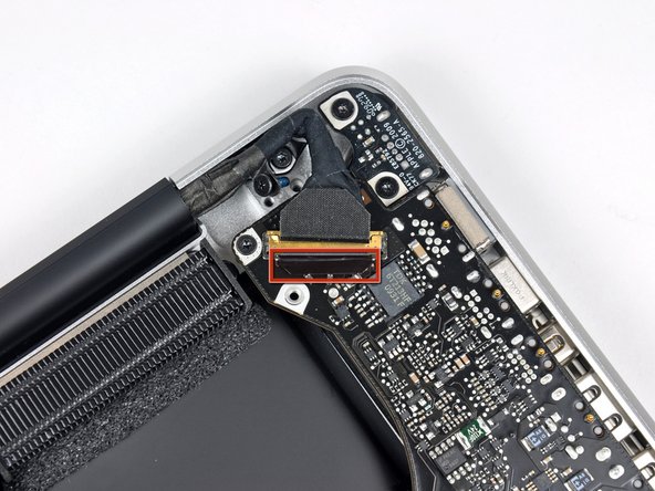
Disconnect the camera cable by pulling the male end straight away from its socket.
-
-
-
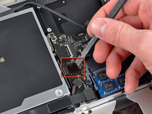
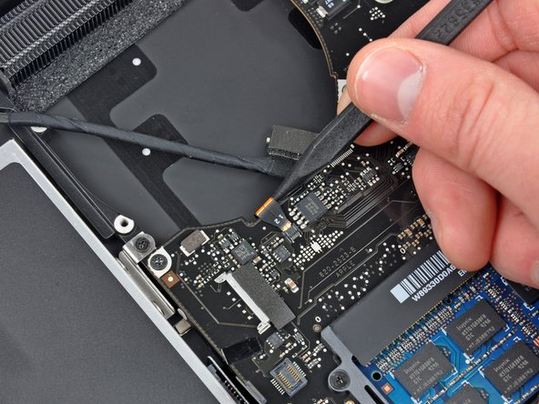
Use the flat end of a spudger to pry the optical drive cable connector up off the logic board.
-
-
-
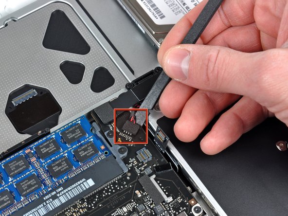
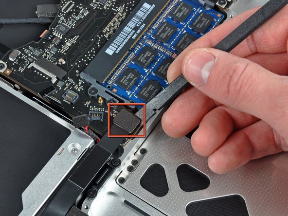
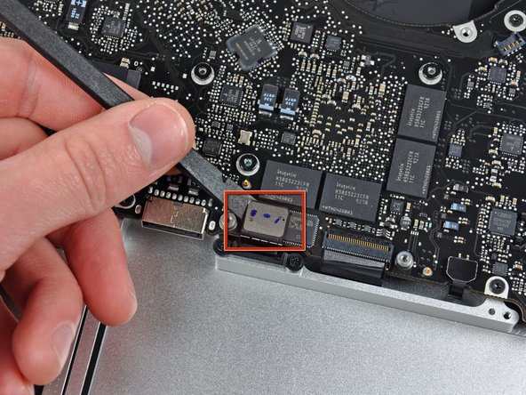
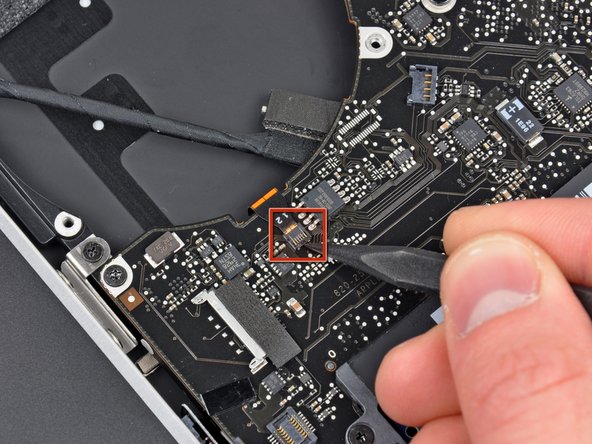
Using the flat end of a spudger, pry the subwoofer connector straight up from the connector jack.
-
-
-
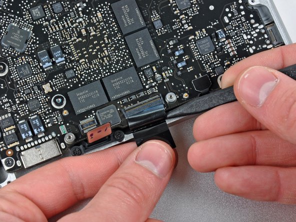
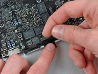
Use the flat end of a spudger to pry the hard drive/IR sensor cable connector up off the logic board.
-
-
-
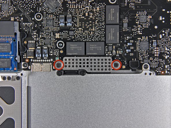
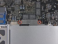
Remove the two 1.5 mm Phillips screws securing the cable cover to the logic board.
-
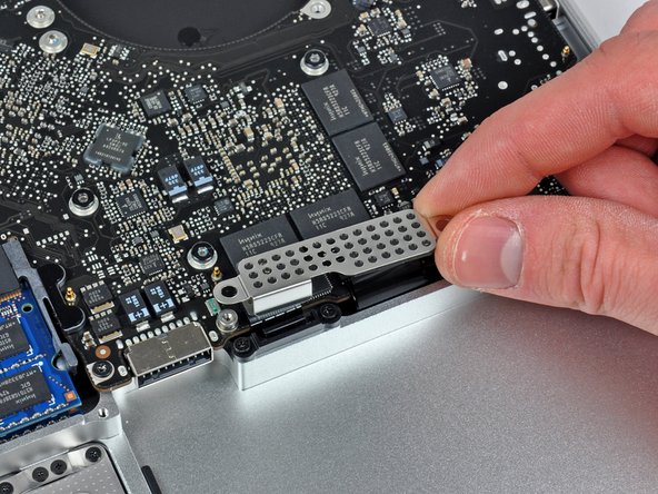
Lift the cable cover out of the upper case.
-
-
-
Use your fingernail to flip up the locking flap on the ZIF socket for the keyboard ribbon cable.
-
Use the tip of a spudger to slide the keyboard ribbon cable out of its socket.
-
-
-
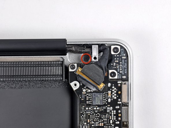
Remove the single 7 mm Phillips screw securing the display data cable retainer to the upper case.
-
Remove the display data cable retainer from the upper case.
-
-
-
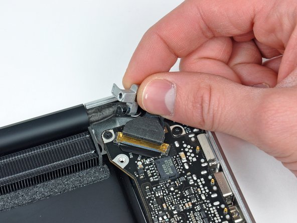
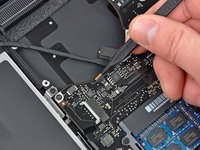
Grab the plastic pull tab secured to the display data cable lock and rotate it toward the DC-in side of the computer.
-
-
-
Using the tip of a spudger, flip up the keyboard backlight ribbon cable retaining flap.
-
Pull the keyboard backlight ribbon cable straight out of its socket.
-
-
-
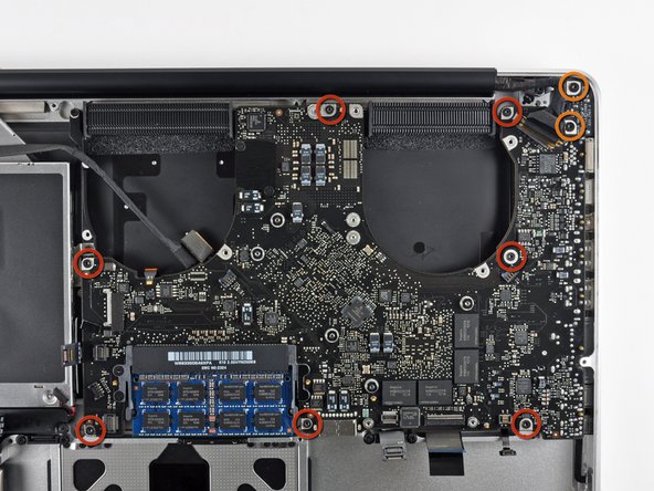
Remove the following screws:
-
Seven 3.3 mm T6 Torx screws securing the logic board to the upper case.
-
Two 8 mm T6 Torx screws securing the DC-In board to the upper case.
-
-
-
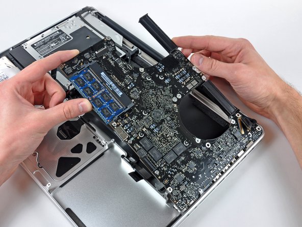
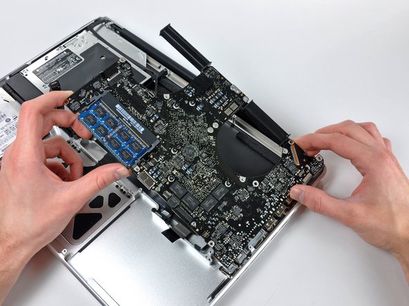
Carefully lift the logic board assembly from the left side and work it out of the upper case, minding the port side that may get caught during removal.
-
-
-
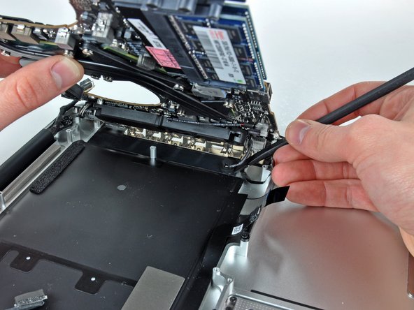
Lift the logic board enough to gain clearance and use a spudger to pry the microphone up off the upper case.
-
Slide the logic board away from the port openings and lift the assembly out of the upper case.
-
-
-
Slide the logic board away from the port openings and lift the assembly out of the upper case.
-
-
-
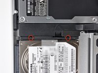
Remove the two Phillips screws securing the hard drive bracket to the upper case.
-
Remove the hard drive bracket from the upper case.
-
-
-
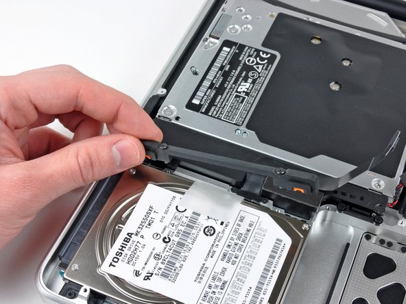
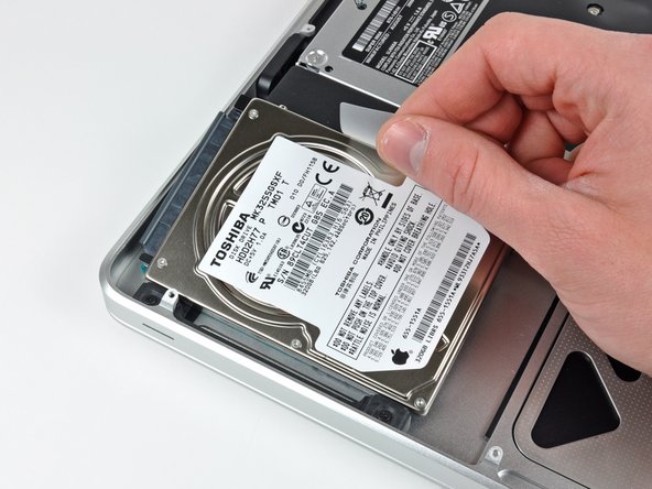
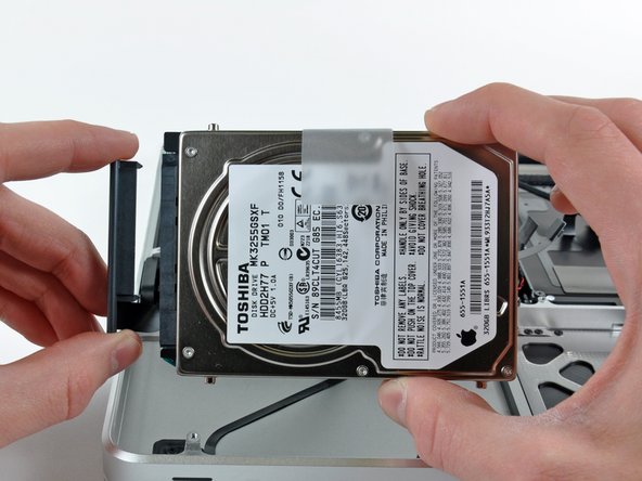
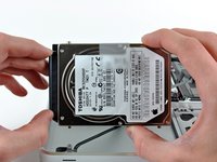
Using its attached tab, lift the free end of the hard drive and pull it away from the edge of the upper case.
-
-
-
Pull the hard drive cable connector away from the body of the hard drive.
-
Remove the hard drive and set it aside.
-
-
-
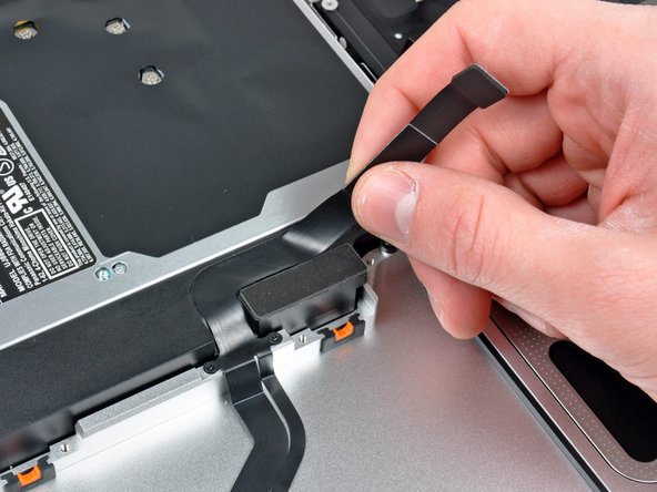
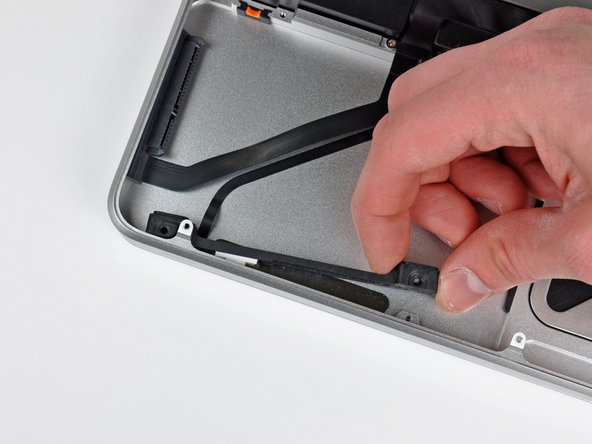
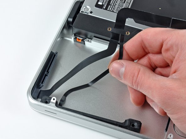
Carefully peel the hard drive cable off the adhesive securing it to the right speaker housing.
-
-
-
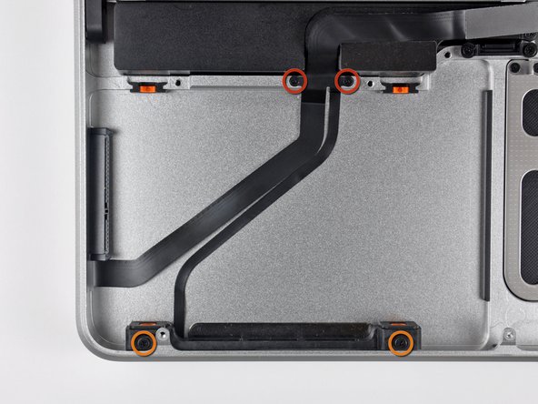
Remove the following four screws securing the hard drive and IR sensor cable to the upper case:
-
Two 1.5 mm Phillips screws.
-
Two 4 mm Phillips screws.
-
-
-
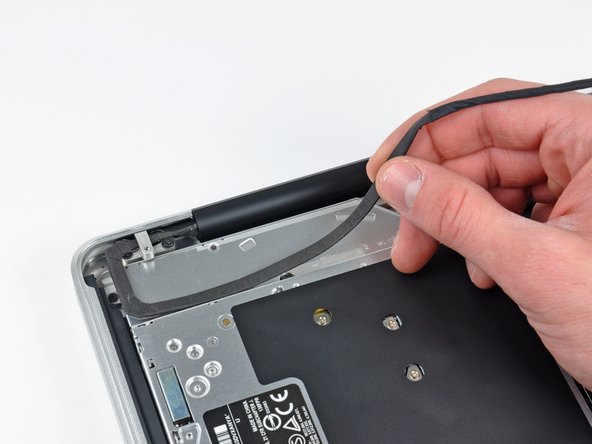
Carefully peel the IR sensor/sleep light ribbon cable off the adhesive securing it to the upper case.
-
-
-
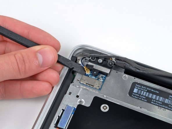
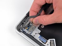
Disconnect the Bluetooth cable by pulling the male end straight away from its socket.
-
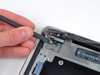
Use the flat end of a spudger to carefully pry the AirPort antenna off its socket on the AirPort card.
-
-
-
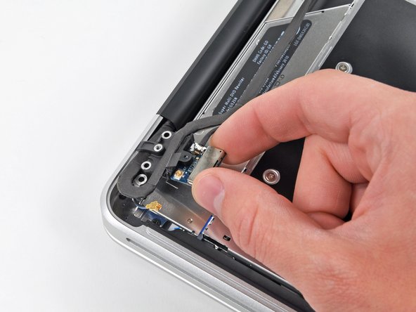
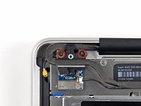
Remove the two 8 mm Phillips screws securing the Bluetooth/camera cable retainer to the upper case.
-
Lift the AirPort board/cable retainer assembly out of the upper case.
-
-
-
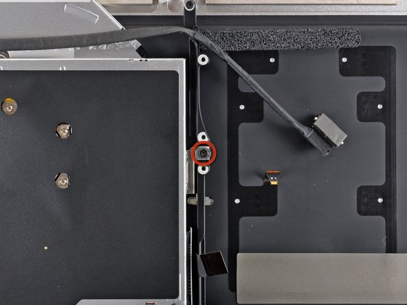
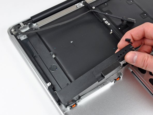
Remove the single 3.5 mm Phillips screw securing the inner side of the optical drive to the upper case.
-
-
-
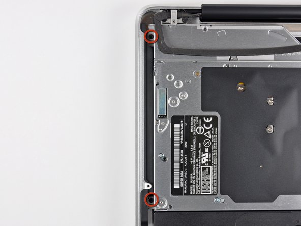
Remove the two 3.5 mm Phillips screws securing the outer side of the optical drive to the upper case.
-
-
-
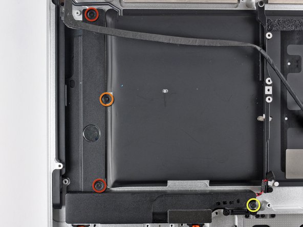
Remove the following four screws securing the subwoofer and right speaker assembly to the upper case:
-
Two 3.2 mm Phillips screws.
-
One 2.6 mm Phillips screw.
-
One 5 mm Phillips screw.
-
-
-
Remove the two 8 mm Phillips screws securing the camera cable retainer to the upper case.
-
Lift the camera cable retainer out of the upper case.
-
-
-
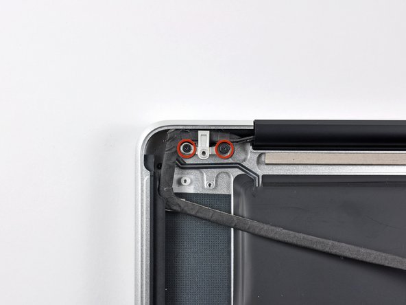
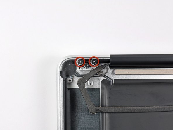
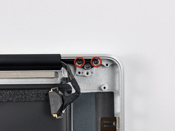
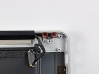
Remove the outer two T6 Torx screws securing both display hinges to the upper case (four screws total).
-
-
-
Open your MacBook Pro so the display is perpendicular to the upper case.
-
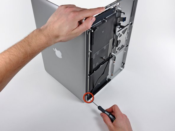
Place your opened MacBook Pro on a table as pictured.
-
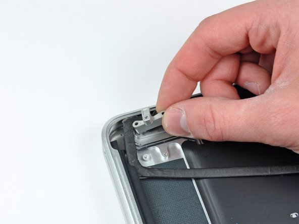
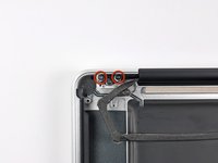
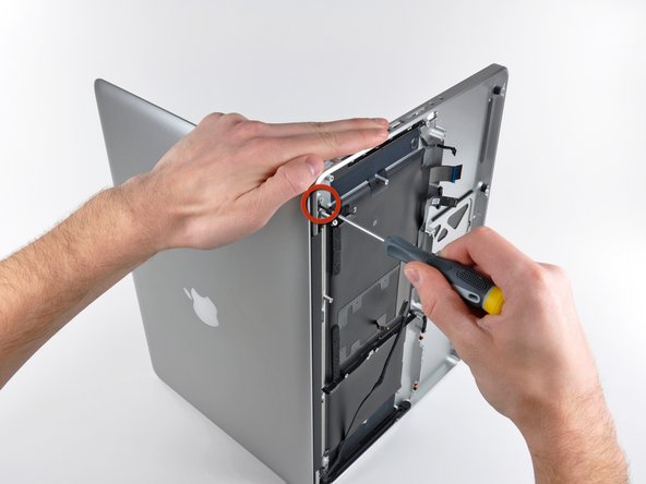
While holding the display and upper case together with your left hand, remove the remaining T6 Torx screw from the lower display bracket.
-
-
-
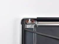
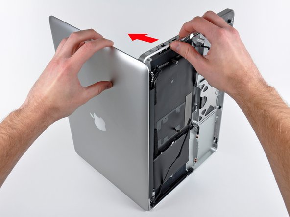
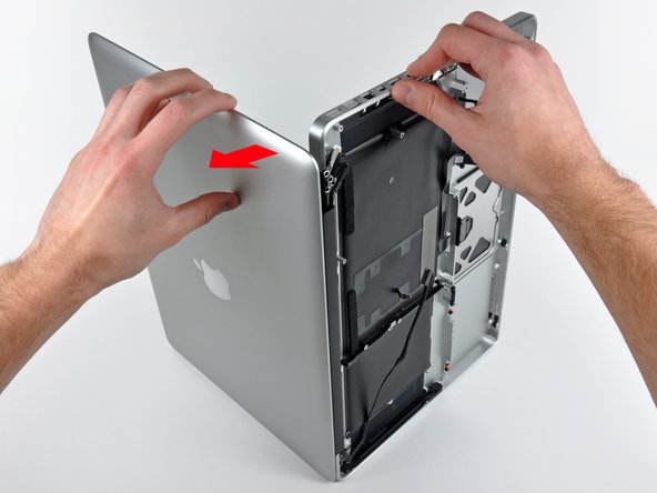
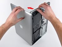
Grab the upper case with your right hand and rotate it slightly toward the top of the display so the upper display bracket clears the edge of the upper case.
-
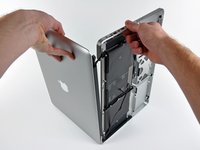
Rotate the display slightly away from the upper case.
-
Lift the display away from the upper case, minding any brackets or cables that may get caught.
-


To reassemble your device, follow these instructions in reverse order.
