
Introduction
Use this guide to replace your upper case. The end of this guide details how to transfer the trackpad to your new upper case.
What you need
-
-
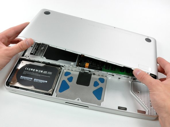
With the case closed, place the Unibody top-side down on a flat surface.
-
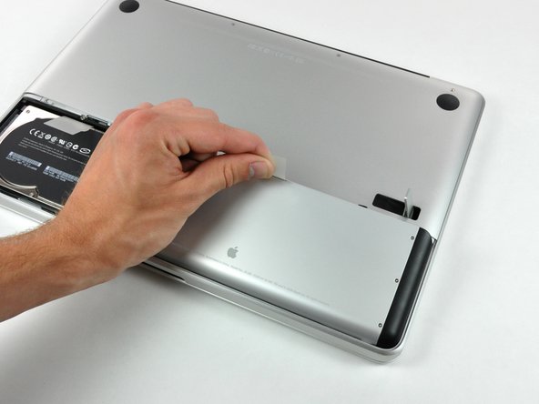
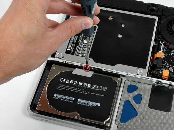
Depress the grooved side of the access door release latch enough to grab the free end. Lift the release latch until it is vertical.
-
-
-
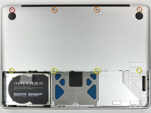
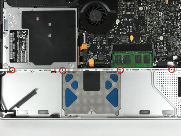
Remove the following eight screws securing the lower case to the chassis:
-
One 3 mm Phillips screw.
-
Three 13.5 mm Phillips screws.
-
Four 3.5 mm Phillips screws.
-
-
-
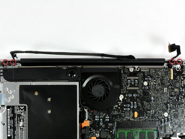
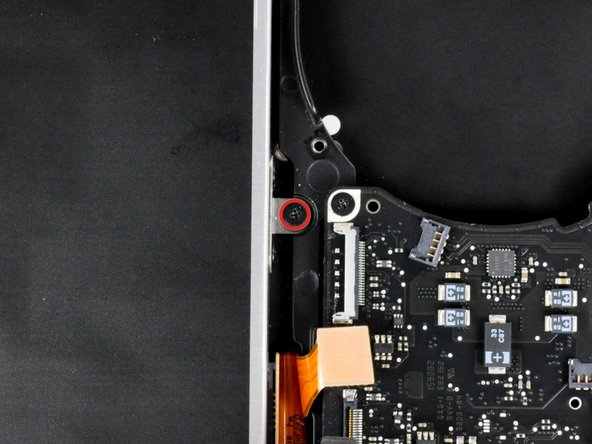
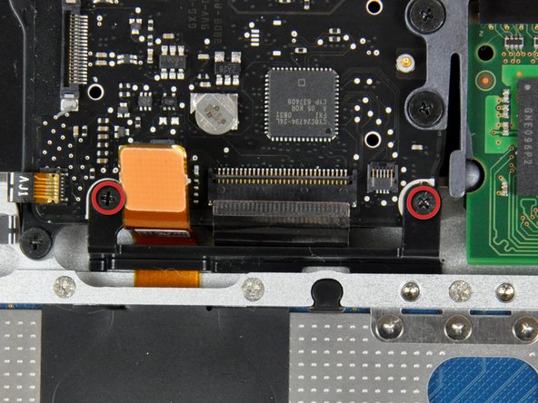
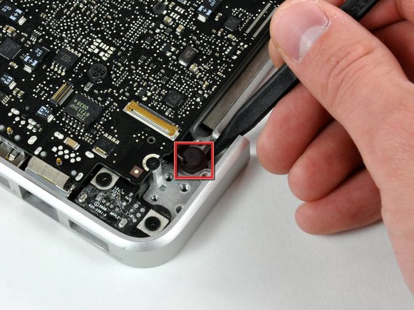
Remove the following screws securing the camera data cable and right speaker to the upper case:
-
One 9.9 mm partially threaded Phillips screw
-
One 9.6 mm threaded Phillips screw
-
One 4 mm Phillips screw
-
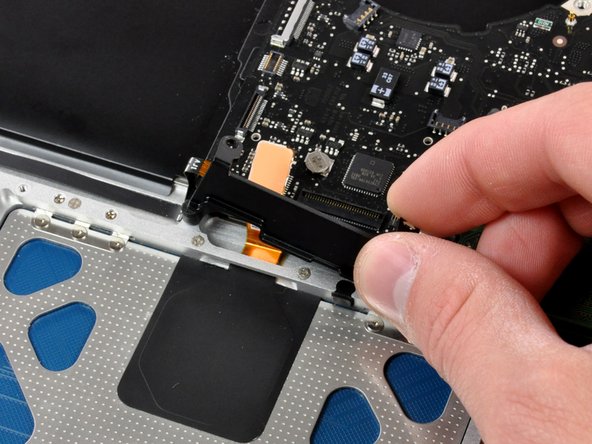
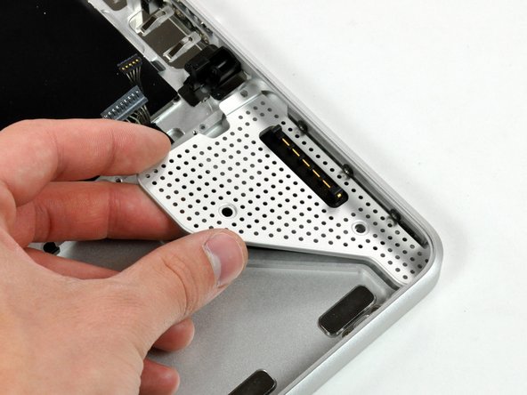
Slide the camera cable bracket out from under the subwoofer and remove it from the computer.
-
-
-
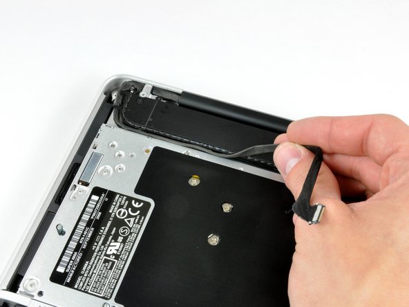
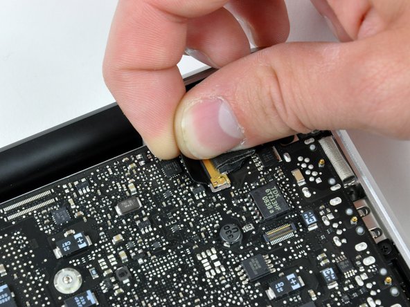
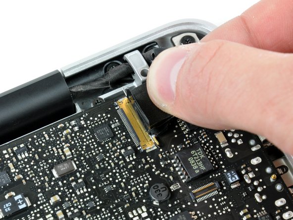
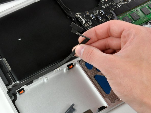
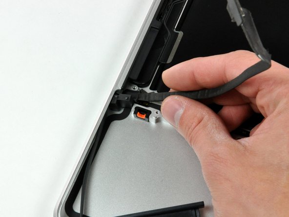
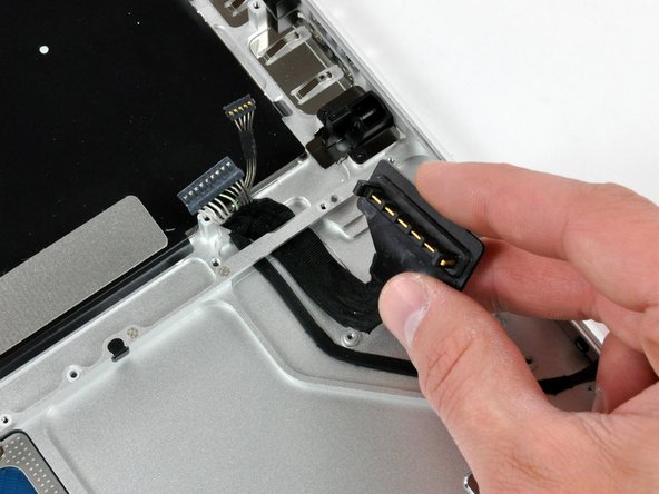
Grab the plastic pull tab secured to the display data cable lock and rotate it toward the DC-in side of the computer.
-
Pull the display data cable connector straight away from its socket.
-
-
-
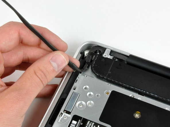
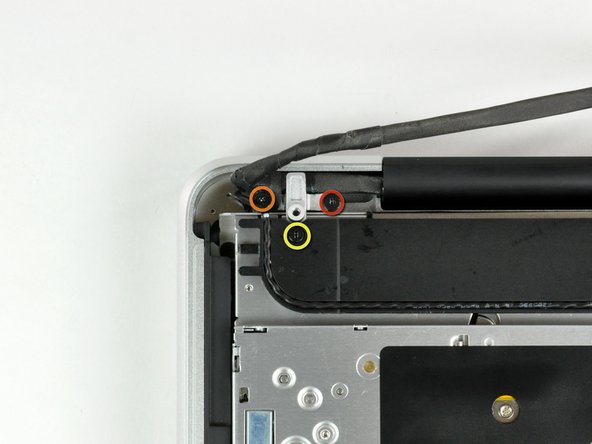
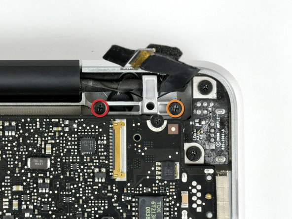
Remove the following two screws from the display data cable bracket:
-
One 7 mm Phillips screw.
-
One 5 mm Phillips screw.
-
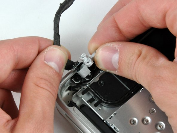
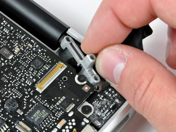
Lift the display data cable bracket out of the upper case.
-
-
-
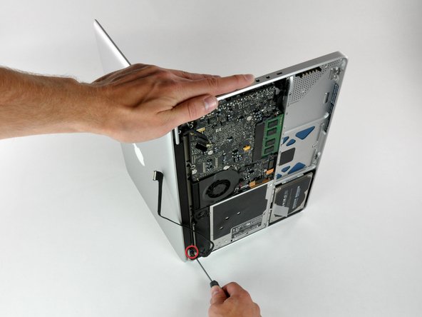
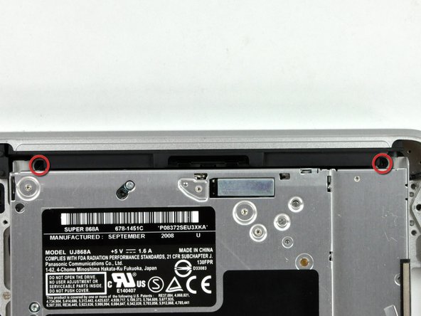
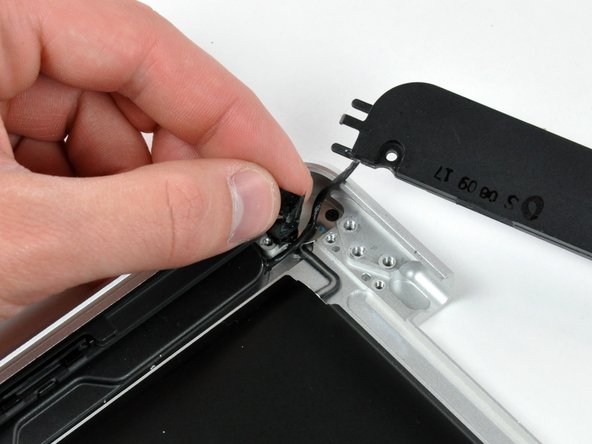
Remove the two outer 6 mm Torx screws securing each side of the display to the upper case (4 screws total).
-
-
-
Open your MacBook so the display is perpendicular to the upper case.
-
Place your opened MacBook on a table as pictured.
-
While holding the display and upper case together with your left hand, remove the 6 mm Torx screw from the lower display bracket.
-
-
-
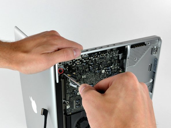
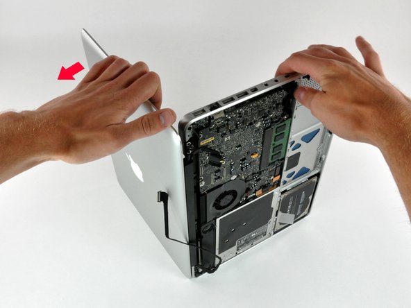
Grab the upper case with your right hand and rotate it slightly toward the top of the display so the upper display bracket clears the edge of the upper case.
-
Rotate the display slightly away from the upper case.
-
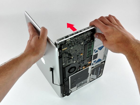
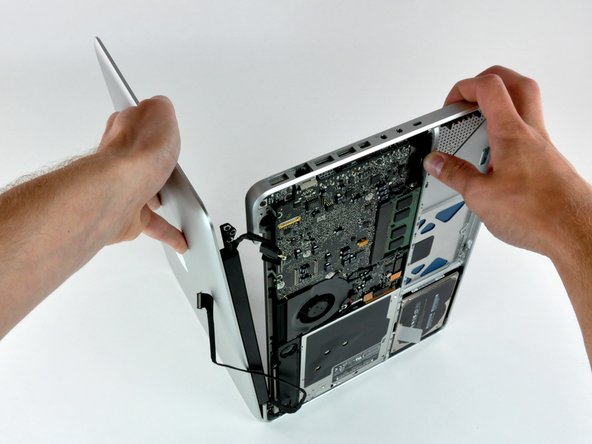
Lift the display away from the upper case, minding any brackets or cables that may get caught.
-
-
-
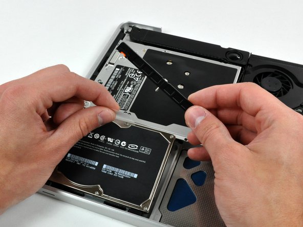
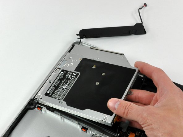
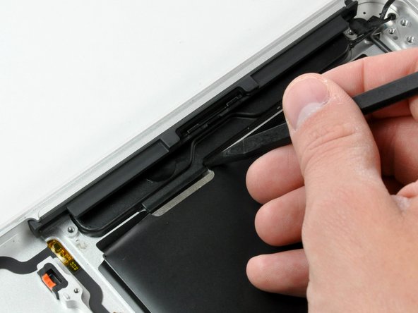
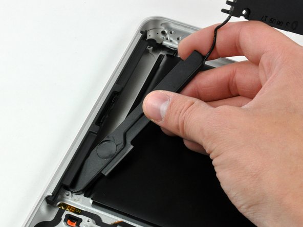
Lift the hard drive by its pull tab enough to grab and remove the retaining bracket.
-
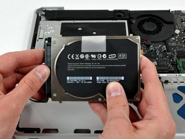
Lift the hard drive out of the chassis, minding the cable attaching it to the computer.
-
-
-
Remove the hard drive from its cable by pulling the cable connector straight away from the drive.
-
-
-
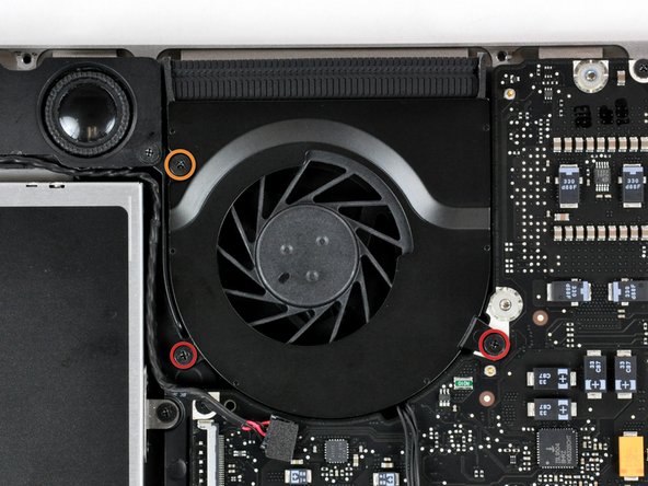
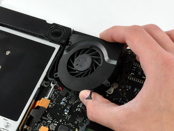
Remove the following three screws securing the fan to the upper case:
-
Two 5 mm Phillips screws.
-
One 7 mm Phillips screw.
-
-
-
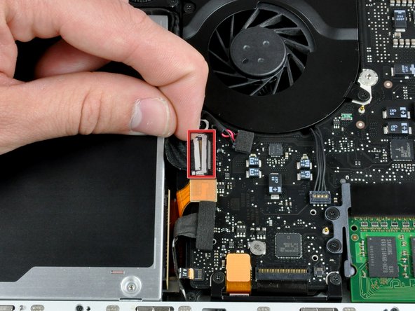
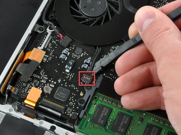
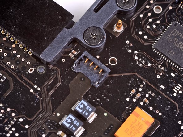
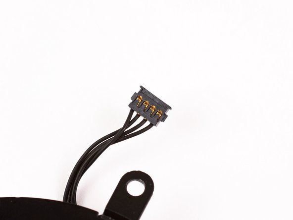
Use a spudger to pry the fan connector straight up and out of its socket on the logic board.
-
-
-
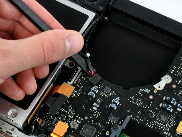
Using the flat end of a spudger, pry the subwoofer connector straight up off the logic board.
-
-
-
Use the flat end of a spudger to pry the hard drive cable connector straight up off the logic board.
-
-
-
Peel the hard drive cable from the adhesive securing it to the upper case, and maneuver the plastic retaining block out of the upper case.
-
-
-
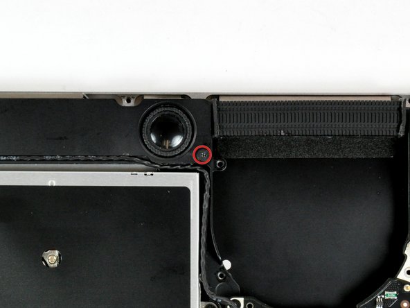
Peel back the small piece of black tape covering the right speaker cable.
-
Use the tip of a spudger to pry the right speaker up off the adhesive securing it to the upper case.
-
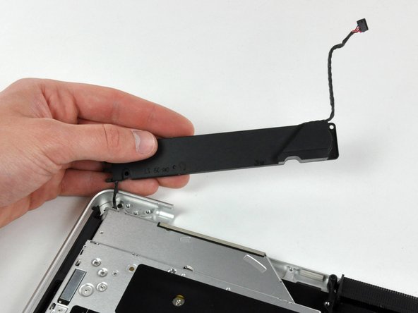
Lift the subwoofer and right speaker assembly out of the upper case.
-
-
-
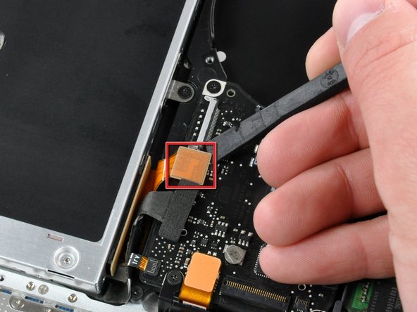
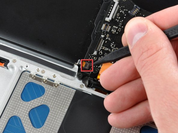
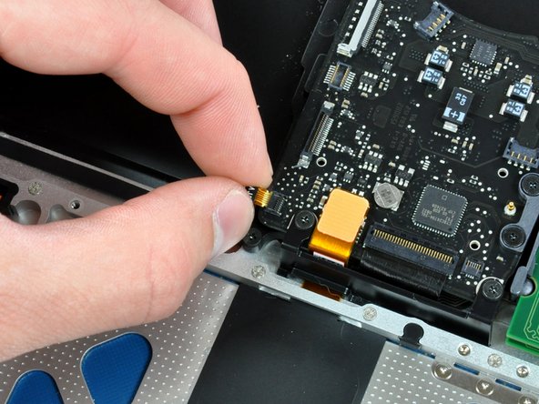
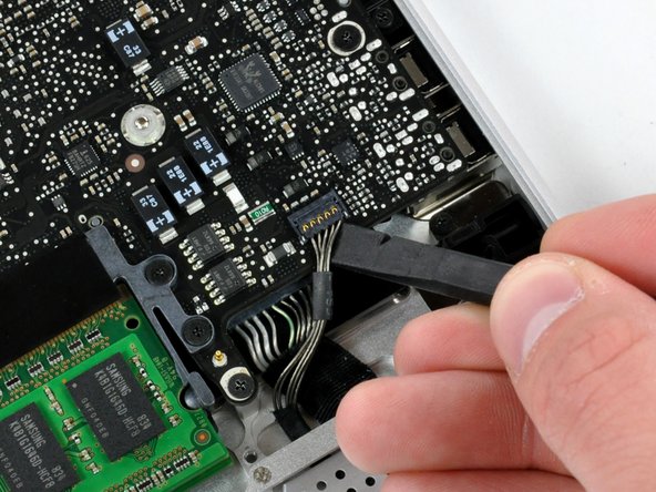
Use the tip of a spudger to flip up the locking lever to release the IR sensor ribbon cable from its socket.
-
Pull the IR sensor ribbon cable straight away from the logic board.
-
-
-
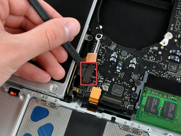
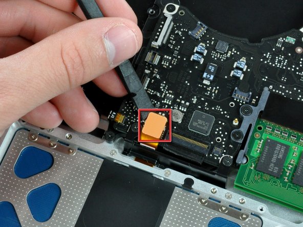
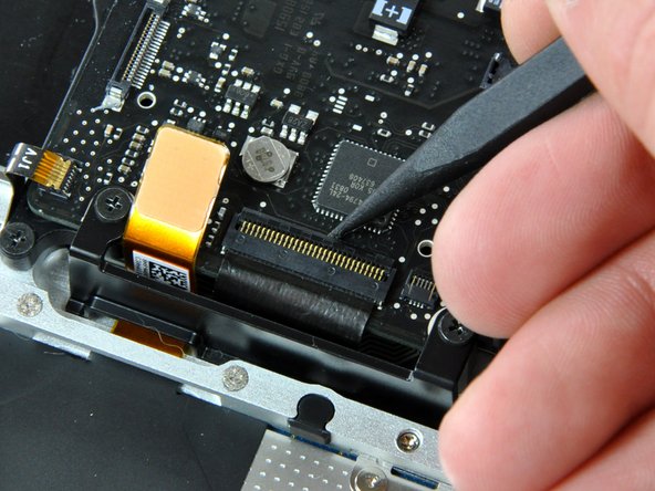
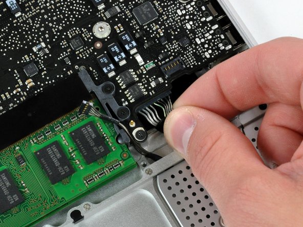
Use the flat end of a spudger to pry the trackpad connector straight up off the logic board.
-
-
-
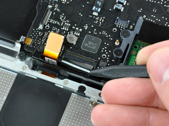
Using the tip of a spudger, flip up the keyboard ribbon cable retaining flap.
-
Pull the keyboard ribbon cable straight out of its socket.
-
-
-
Remove the two 5 mm Phillips screws securing the keyboard flex bracket to the upper case.
-
Lift the keyboard flex bracket out of the upper case.
-
-
-
Remove the single Phillips screw securing the battery cable cover to the upper case.
-
Remove the battery cable cover from the upper case.
-
-
-
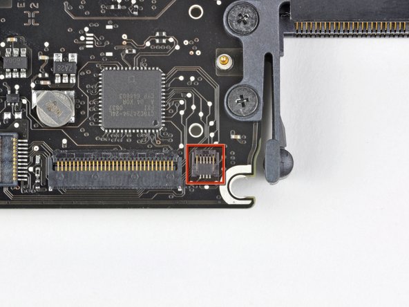
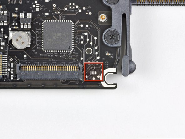
Use a spudger to pry the battery level indicator cable connector straight up off the logic board.
-
-
-
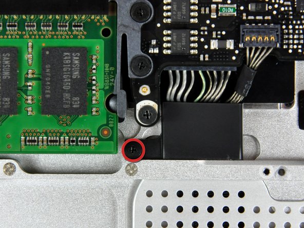
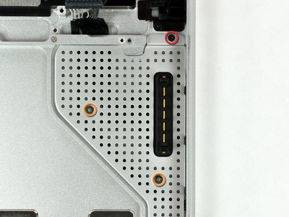
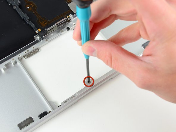
Remove the two 4mm Phillips screws securing the bottom case clip to the upper case.
-
Lift the bottom case clip out of the upper case.
-
-
-
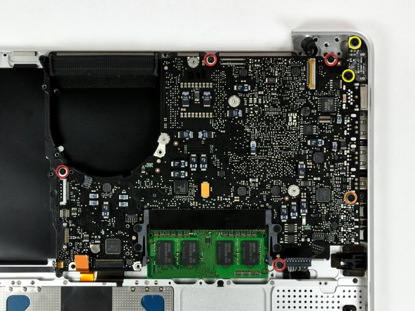
Remove the following five screws securing the logic board to the upper case:
-
Four 3 mm Phillips screws.
-
One 3.5 mm Phillips screw.
-
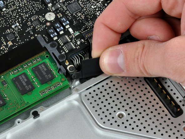
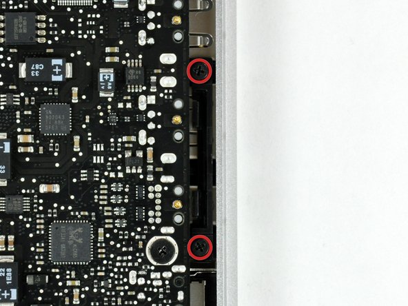
Remove the two 7 mm Phillips screws securing the DC-in board to the upper case.
-
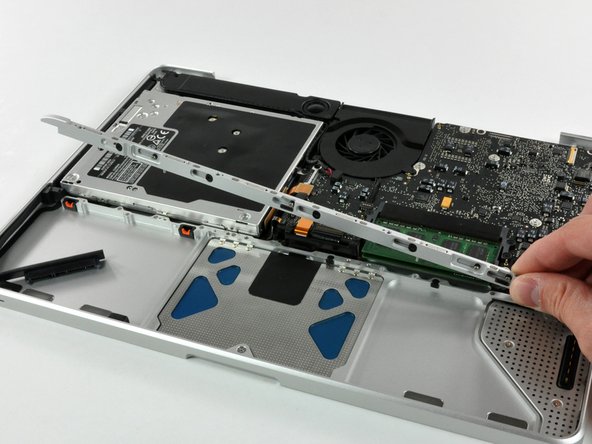
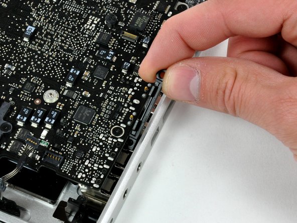
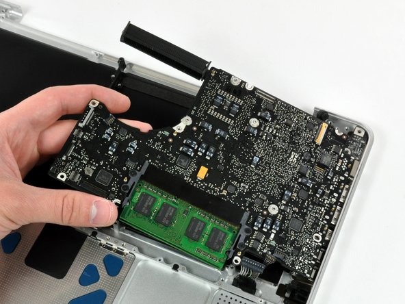
Lift the logic board from its left edge and pull it out of the upper case.
-
-
-
Remove the following screws securing the battery connector cover to the upper case:
-
One 2.5 mm Phillips screw.
-
Two 1.5 mm Phillips screws.
-
Lift the battery connector cover out of the upper case.
-
-
-
De-route the battery connector cable through the gap in the upper case and remove it from the computer.
-
-
-
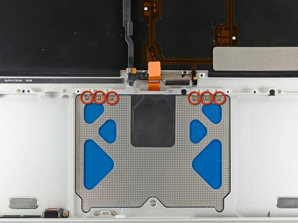
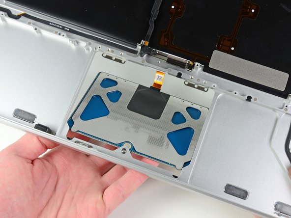
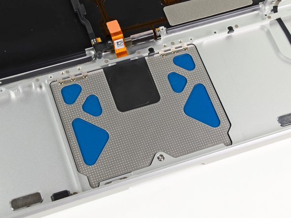
Carefully dislodge the edge of the trackpad closest to the keyboard from its recess in the upper case by pushing it away from the brackets attached to the upper case.
-
De-route the trackpad cable through its slot cut into the upper case.
-
-
-
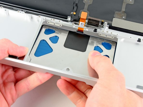
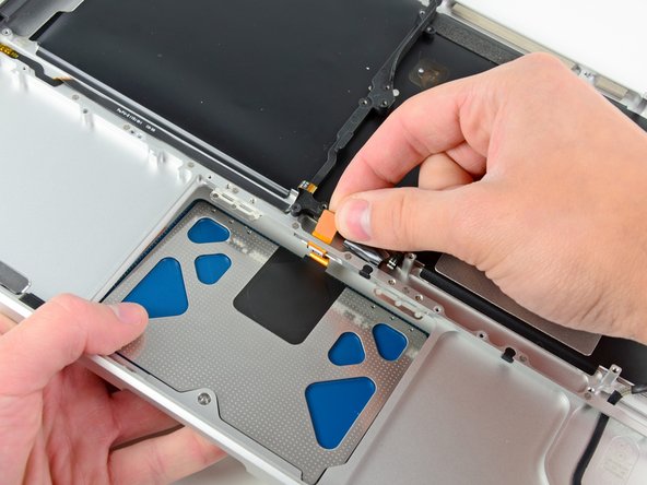
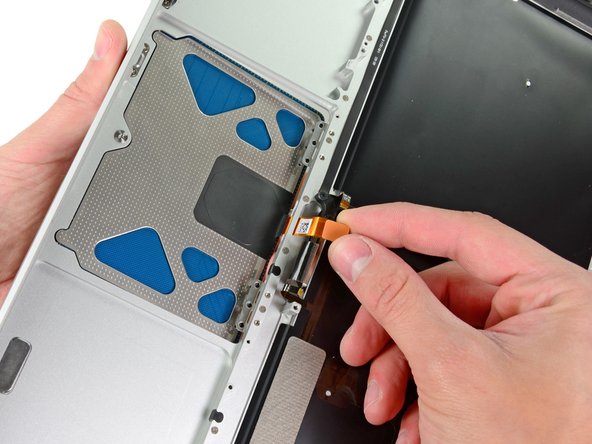
Pull the trackpad away from the outer edge of the upper case.
-
Remove the trackpad and set it aside.
-
-
-
Use a Y1 Tri-wing screwdriver to loosely install the 1.2 mm set screw included with your new upper case into its tapped hole near the middle of the trackpad opening on your new upper case.
-
-
-
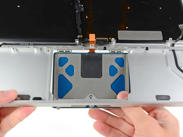
Carefully insert the cable from your old trackpad through its slot cut into your new upper case.
-
Use one hand to hold the trackpad cable in place as you insert the two retaining tabs on the outer edge of the trackpad under the lip on the upper case.
-
Pull the trackpad cable as you seat the trackpad into its void in your new upper case.
-
-
-
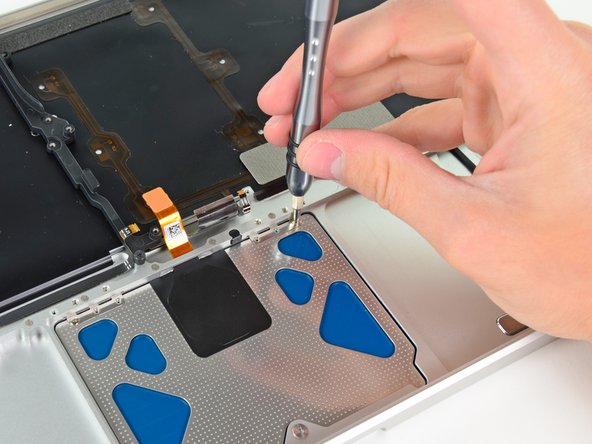
Insert a 1.4 mm Y0 Tri-wing screw into each of the outer holes drilled into the trackpad (two screws total).
-
-
-
While continually trying to click your trackpad, gently tighten the Y1 Tri-wing set screw until the clicks return to their factory "feel".
-
-
-
Next, flip your upper case over so the keyboard side is facing up.
-
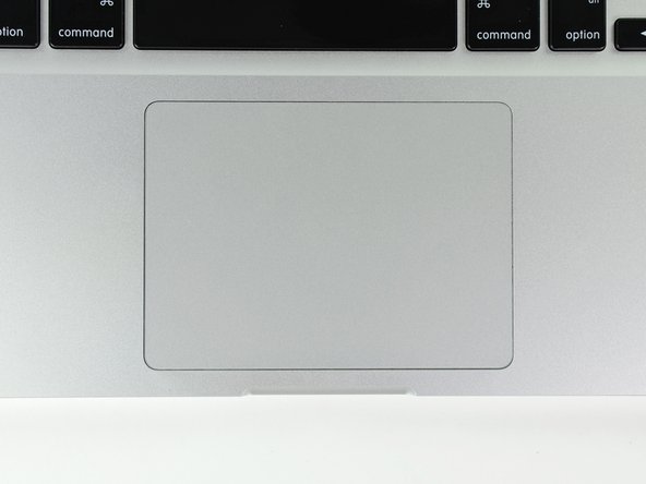
Align the trackpad so it is centered in its hole cut into the upper case.
-
-
-
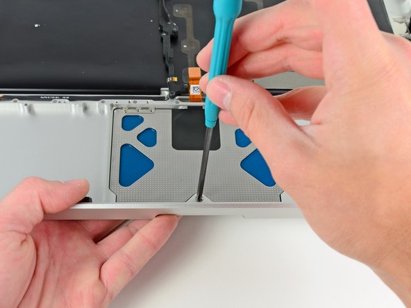
Tighten the outer two screws along the inner edge of the trackpad and check the alignment of it on the outer side of the upper case.
-
If its alignment looks good, install the rest of the Y0 Tri-wing screws along the inner edge of the trackpad.
-
Before reassembling your machine, verify that the set screw is still installed in a position so the mouse will click correctly.
-


To reassemble your device, follow these instructions in reverse order.
To reassemble your device, follow these instructions in reverse order.
