
Introduction
Use this guide to completely replace your logic board.
What you need
-
-
Remove the eight 4 mm Phillips screws securing the lower case to the MacBook.
-
-
-
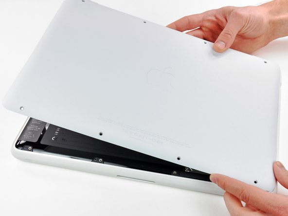
Slightly lift the lower case near the vent opening.
-
Continue running your fingers between the lower and upper cases until the upper case pops off its retaining clips.
-
-
-
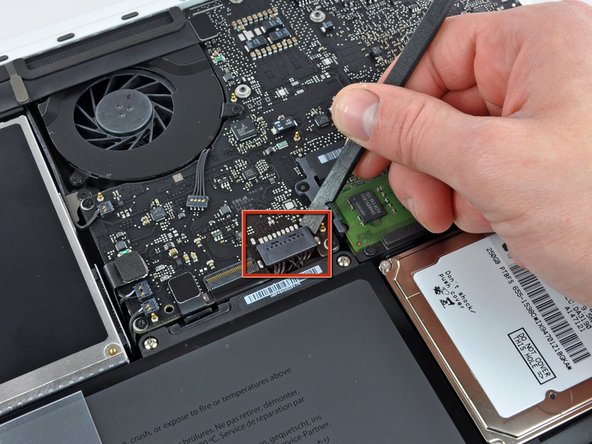
Use the flat end of a spudger to lift the battery connector up out of its socket on the logic board.
-
-
-
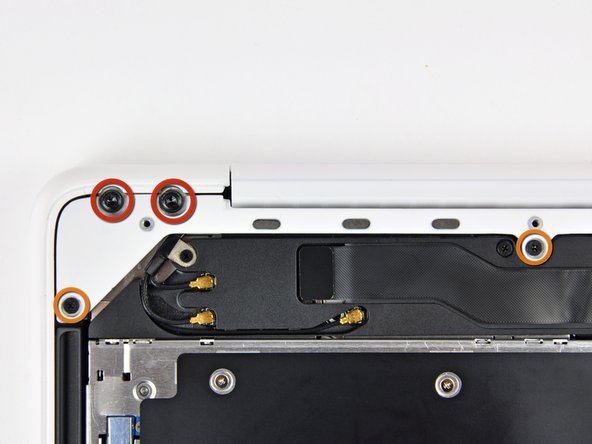
Remove the following screws from the optical drive side of the rear vent:
-
Two 10 mm T8 Torx
-
Two 5.2 mm Phillips
-
-
-
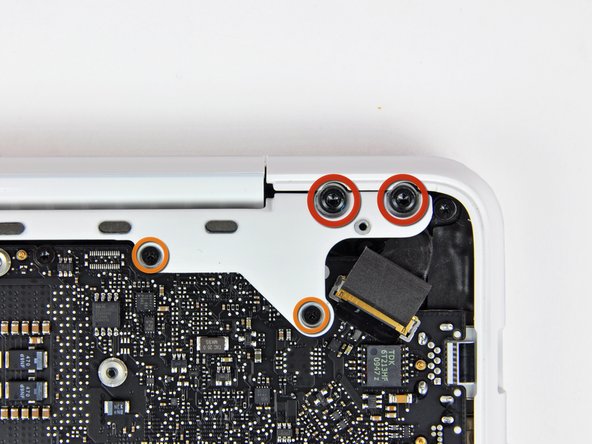
Remove the following screws from the port side of rear vent:
-
Two 10 mm T8 Torx
-
Two 5.2 mm Phillips
-
-
-
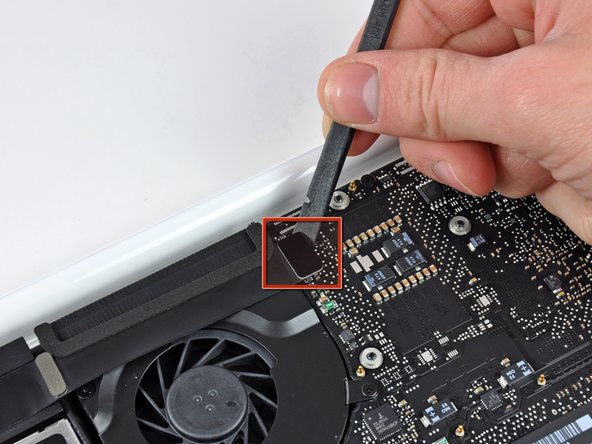
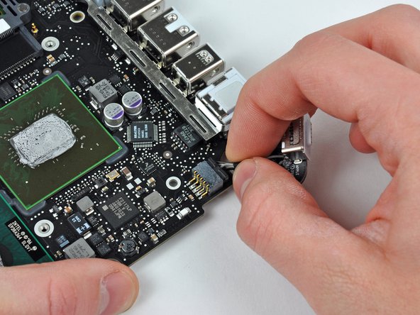
Use the flat end of a spudger to pry the AirPort/Bluetooth ribbon cable up off the logic board.
-
-
-
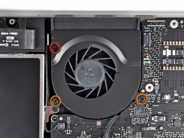
Remove the following three screws securing the fan to the upper case:
-
One 7.1 mm Phillips screw.
-
Two 5 mm Phillips screws.
-
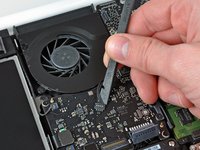
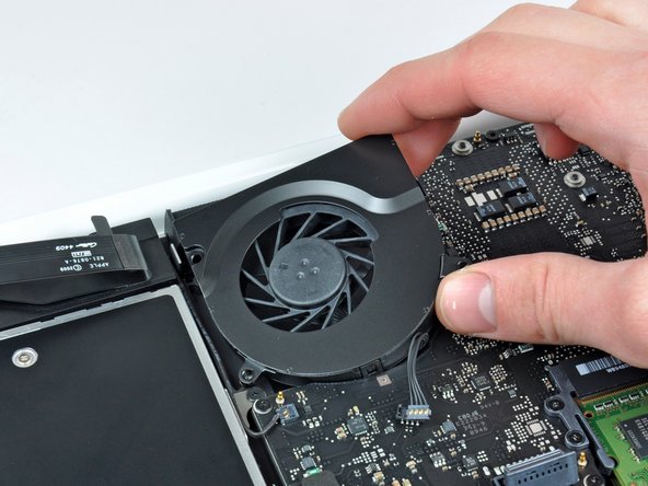
Lift the fan out of the upper case.
-
-
-
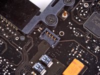
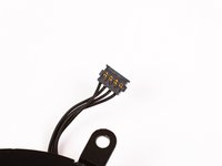
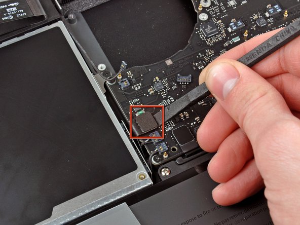
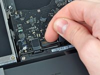
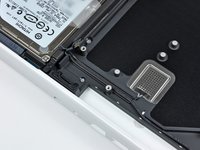
Carefully pry the delicate rear speaker connector up off the logic board. These small L/R speaker connectors are quite easily broken.
-
-
-
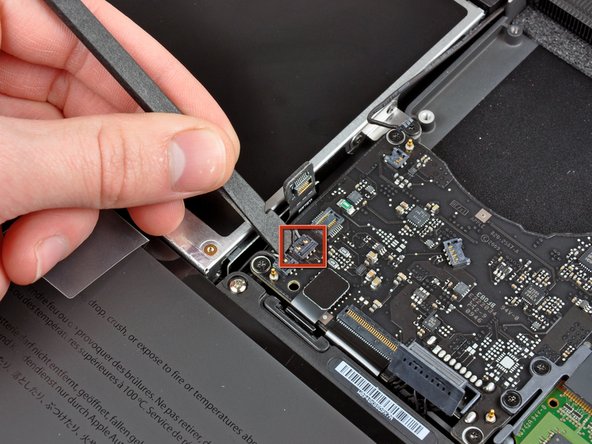
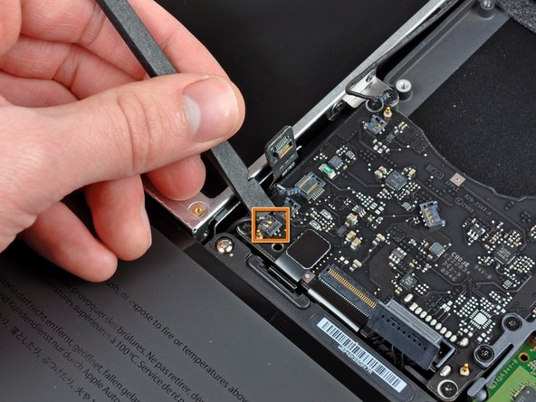
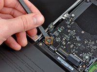
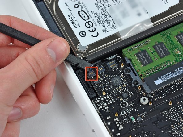
Use a spudger to pry the right speaker connector and sleep LED connector up off the logic board.
-
-
-
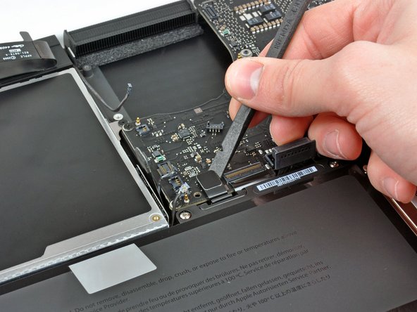
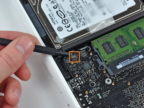
Use the flat end of a spudger to pry the trackpad ribbon cable connector up off the logic board.
-
-
-
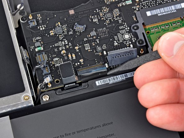
Use your fingernail to flip up the locking flap on the ZIF socket for the keyboard ribbon cable.
-
Use the tip of a spudger to slide the keyboard ribbon cable out of its socket.
-
-
-
Use a spudger to pry the left speaker connector and microphone connector up off the logic board.
-
-
-
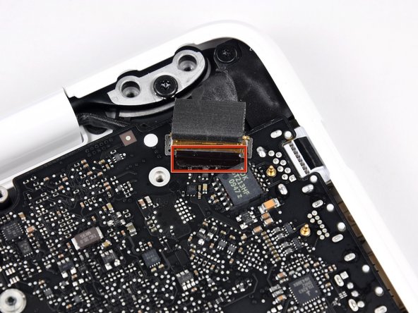
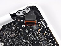
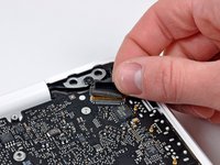
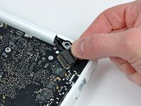
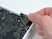
Grab the plastic pull tab secured to the display data cable lock and rotate it toward the DC-In side of the computer.
-
-
-
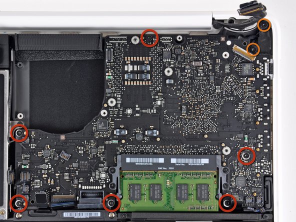
Remove the six 4.1 to 4.4 mm T6 Torx screws securing the logic board to the upper case.
-
Remove the two 4.1 to 4.5 mm T6 Torx screws securing the MagSafe board to the upper case.
-
On some models, these screws may be T7. Be careful not to strip away the head with a smaller bit.
-
-
-
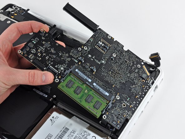
Lift the side of the logic board opposite the ports out of the upper case.
-
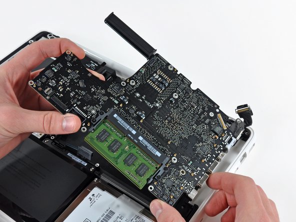
Rotate the logic board away from the upper case until the ports clear the lip molded in the upper case.
-
Pull the logic board and MagSafe board away from the edge of the upper case as one piece.
-
-
-
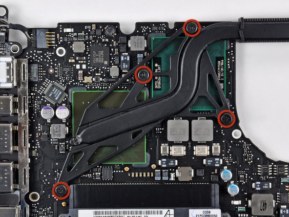
Remove the four 8.3 mm shouldered Phillips screws securing the heat sink to the logic board.
-
-
-
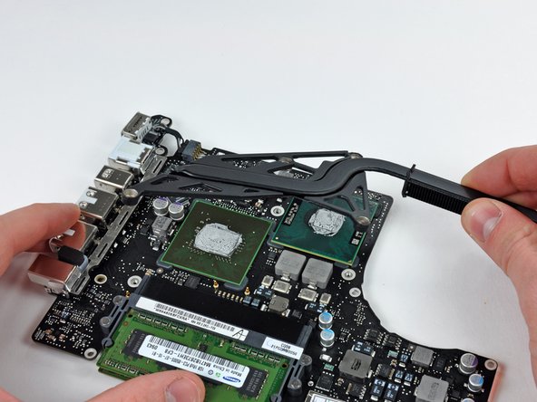
Carefully flip the logic board over.
-
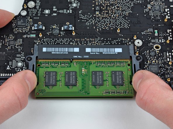
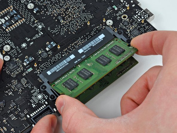
Release the tabs on each side of the chip by simultaneously pushing each tab away from the RAM.
-


To reassemble your device, follow these instructions in reverse order.
