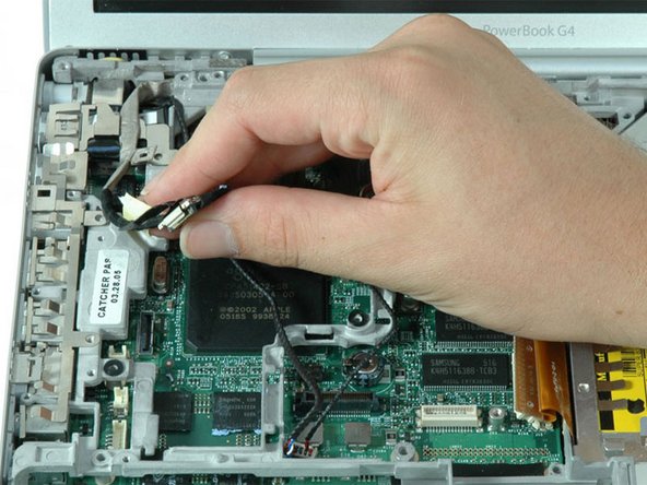
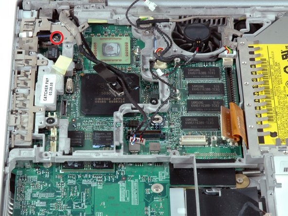
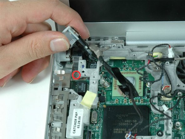
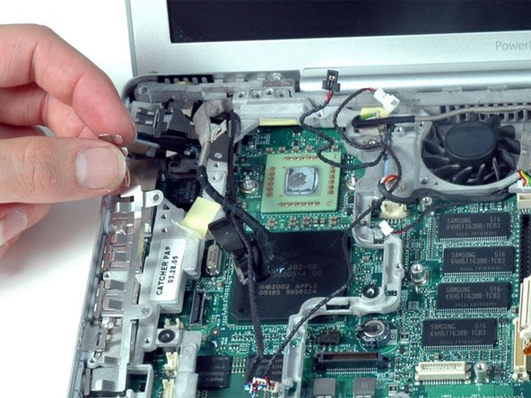
PowerBook G4 Aluminum 12" 1-1.5 GHz Fan Replacement

What you need

    1. PowerBook G4 Aluminum 12" 1-1.5 GHz Fan Replacement, PowerBook G4 Aluminum 12" 1-1.5 GHz Fan Replacement: step 1, image 1 of 1
      • Use a coin to turn the battery locking screw 90 degrees to the right.

      • Lift the battery out of the computer.

      Add Comment

    2. PowerBook G4 Aluminum 12" 1-1.5 GHz Fan Replacement: step 2, image 1 of 1
      • Remove the four Phillips screws from the memory door.

      • Slide the memory door away from the memory compartment.

      Add Comment

    3. PowerBook G4 Aluminum 12" 1-1.5 GHz Fan Replacement: step 3, image 1 of 1
      • Remove the long black Phillips screw next to the memory card.

      • Remove the small EMI finger beneath the black screw.

      Add Comment

    4. PowerBook G4 Aluminum 12" 1-1.5 GHz Fan Replacement: step 4, image 1 of 1
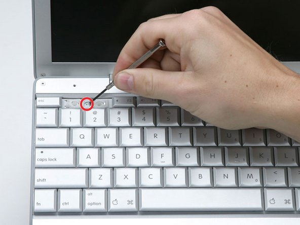
      • On the keyboard, remove the F1, F2, F11, and F12 keys.

      • This is scary - take a deep breath before continuing. Place your index finger under the upper left corner of the key and lift up until you hear a click. Then, transfer your finger to the left edge of the key and lift up to pull the key off.
      • You're freeing the two tabs on the left of the key from the two small holes in the plastic scissors mechanism.

      • When replacing the keys in the keyboard, place the key directly over the slot where it will go and press down until you hear the key click into place.

      Add Comment

    5. PowerBook G4 Aluminum 12" 1-1.5 GHz Fan Replacement: step 5, image 1 of 1
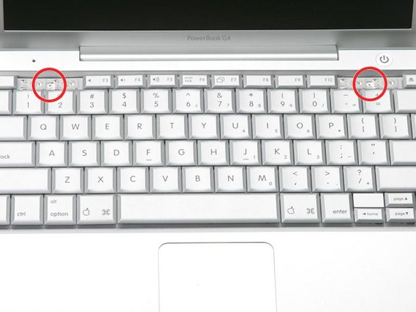
      • Use your fingernail or a small flathead screwdriver to peel up the gray stickers covering each of the screws.

      Add Comment

    6. PowerBook G4 Aluminum 12" 1-1.5 GHz Fan Replacement: step 6, image 1 of 1
      • Remove the two short Phillips screws.

      Add Comment

    7. PowerBook G4 Aluminum 12" 1-1.5 GHz Fan Replacement: step 7, image 1 of 1
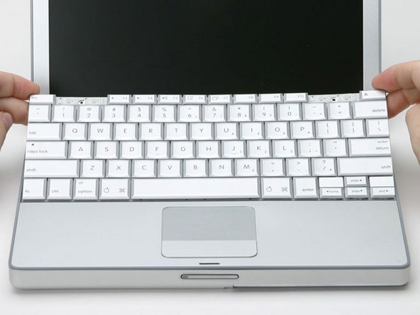
      • Lift the keyboard by the 'esc' and 'eject' keys and gently lift up until the keyboard is vertical.

      Add Comment

    8. PowerBook G4 Aluminum 12" 1-1.5 GHz Fan Replacement: step 8, image 1 of 1
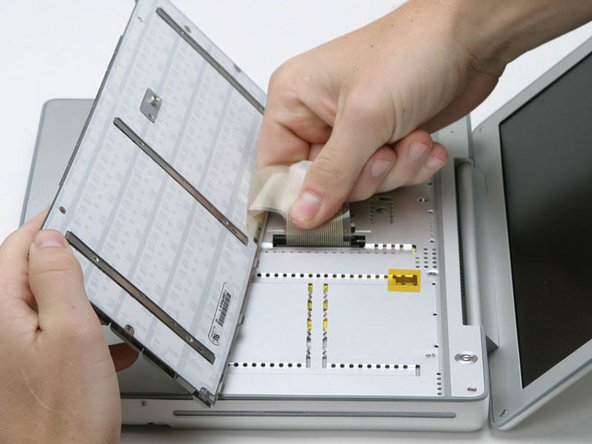
      • Grasp the keyboard connector ribbon near the connector and disconnect it from the logic board.

      Add Comment

    9. PowerBook G4 Aluminum 12" 1-1.5 GHz Fan Replacement: step 9, image 1 of 1
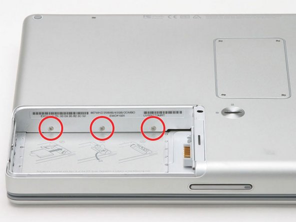
      • Remove the three 2.5mm Phillips screws from within the battery compartment.

      Add Comment

    10. PowerBook G4 Aluminum 12" 1-1.5 GHz Fan Replacement: step 10, image 1 of 1
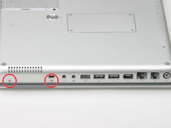
      • Turn the computer 90 degrees clockwise and remove the two Phillips screws from the casing.

      • Outside case screws are aprox. 1/4 in long

      Add Comment

    11. PowerBook G4 Aluminum 12" 1-1.5 GHz Fan Replacement: step 11, image 1 of 1
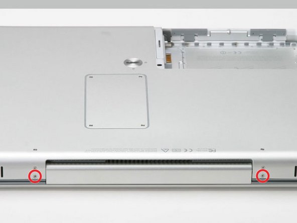
      • Turn the computer 90 degrees clockwise again, and remove only the bottom screw on either side of the hinge.

      Add Comment

    12. PowerBook G4 Aluminum 12" 1-1.5 GHz Fan Replacement: step 12, image 1 of 1
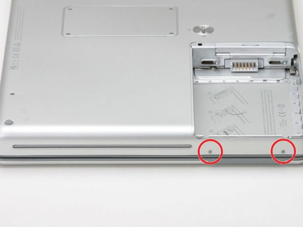
      • Turn the computer 90 degrees clockwise just one more time, and remove the two Phillips screws on the exterior wall of the battery compartment.

      • Note: For reassembly the two screws have long necks.

      Add Comment

    13. PowerBook G4 Aluminum 12" 1-1.5 GHz Fan Replacement: step 13, image 1 of 1
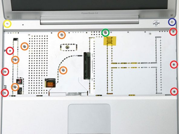
      • Turn the computer over and open it up.

      • Remove the following 14 screws:

      • Six 2.5 mm Phillips on either side of the keyboard area.

      • Five 4.5 mm Phillips on the left half of the keyboard area.

      • One 7 mm hex in the upper left corner of the upper case (a T6 Torx driver will do the job nicely).

      • One 15 mm Phillips in the upper middle of the keyboard area.

      • One 16.5 mm hex in the upper right of the upper case (again, a T6 Torx driver will work well).

      Add Comment

    14. PowerBook G4 Aluminum 12" 1-1.5 GHz Fan Replacement: step 14, image 1 of 1
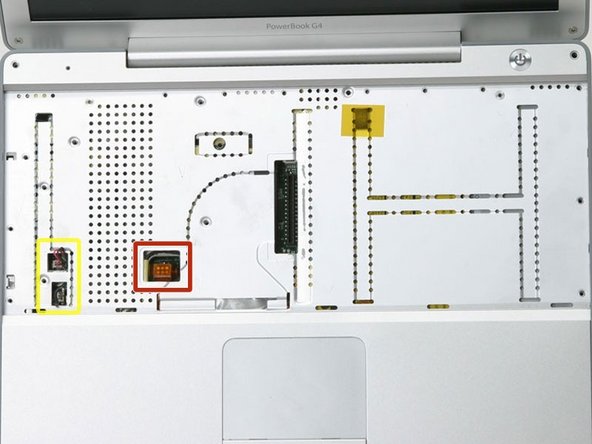
      • This step is extremely tricky, and has the potential to ruin your computer. It is easy to pull the plug with the red and black leads (the power) out of the motherboard. If you do that, it is nearly impossible to fix.

      • Peel up the two pieces of foil tape on the left side of the keyboard area.

      • The connectors at the ends of the cables are attached very firmly to the sockets on the logic board. Pulling directly on the cable will either separate the cable from its connector or the socket from the logic board.

      • Carefully disconnect the microphone and power cables from the logic board. Using your fingernails or a dental pick, carefully pry the connectors from their sockets. Make sure you're pulling only on the connector and not on the socket.

      Add Comment

    15. PowerBook G4 Aluminum 12" 1-1.5 GHz Fan Replacement: step 15, image 1 of 1
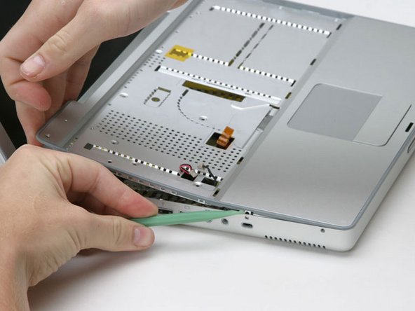
      • Starting at one of the upper corners near the screen, work around the frame, separating the upper case from the lower case.

      Add Comment

    16. PowerBook G4 Aluminum 12" 1-1.5 GHz Fan Replacement: step 16, image 1 of 1
      • Using a screw driver, gently release the two grey plastic clips inside the battery compartment in order to remove the right part of the upper case.

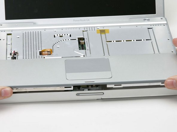
      • There are two more grey plastic clips holding the left part of the upper case. They are not easy to release as they are hidden from view prior to disassembly. They are in the same position as the two in the battery compartment, but on the opposite side of the trackpad. Try to stick a flat pry tool into the clip holes and push the clips inward (toward to screen) so they disengage and release the left part of the upper case.

      • Lift the upper case off the computer.

      Add Comment

    17. PowerBook G4 Aluminum 12" 1-1.5 GHz Fan Replacement: step 17, image 1 of 1
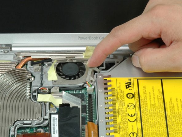
      • Peel back the yellow tape securing the inverter cable near the fan.

      Add Comment

    18. PowerBook G4 Aluminum 12" 1-1.5 GHz Fan Replacement: step 18, image 1 of 1
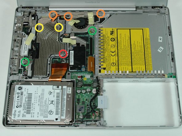
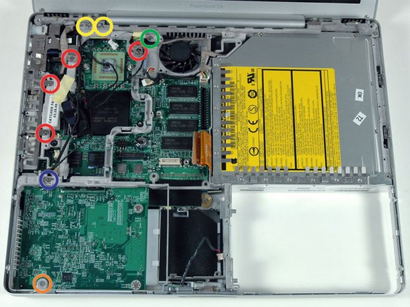
      • Remove the following eight screws:

      • One 4.5 mm Phillips near the modem.

      • Three 6 mm Phillips near the display.

      • Two large 7.5 mm Phillips with attached springs.

      • Two 13 mm Phillips, one on the lower left side of the heat sink and one between the fan and the optical drive.

      Add Comment

    19. PowerBook G4 Aluminum 12" 1-1.5 GHz Fan Replacement: step 19, image 1 of 1
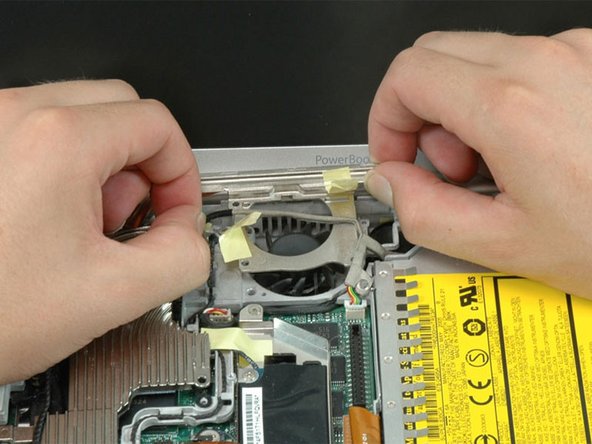
      • Peel up the Bluetooth cable on the right side of the fan.

      Add Comment

    20. PowerBook G4 Aluminum 12" 1-1.5 GHz Fan Replacement: step 20, image 1 of 1
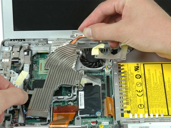
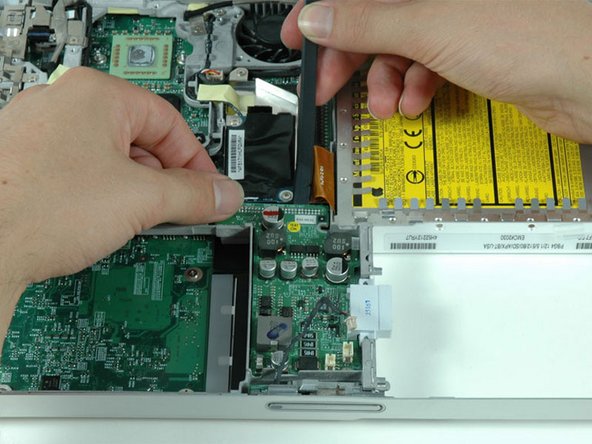
      • Lift up the inverter cable with one hand, and carefully thread it around the heat sink. The inverter cable is still attached to the logic board, so be careful not to put too much strain on the cable.

      Add Comment

    21. PowerBook G4 Aluminum 12" 1-1.5 GHz Fan Replacement: step 21, image 1 of 1
      • Support the heat sink with both hands, and carefully lift it out of the computer. Be careful not to bend the copper heat pipe connecting the two sections of the heat sink.

      • If you need to mount the heat sink back into the laptop, we have a thermal paste guide that makes replacing the thermal compound easy.

      Add Comment

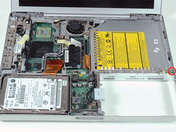
    22. PowerBook G4 Aluminum 12" 1-1.5 GHz Fan Replacement: step 22, image 1 of 1
      • Remove the single Phillips screw securing the hall effect sensor board to the optical drive.

      Add Comment

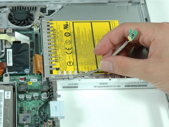
    23. PowerBook G4 Aluminum 12" 1-1.5 GHz Fan Replacement: step 23, image 1 of 1
      • Deroute the cable connecting the hall effect sensor board to the DC-to-DC board.

      Add Comment

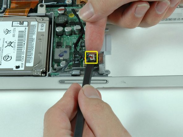
    24. PowerBook G4 Aluminum 12" 1-1.5 GHz Fan Replacement: step 24, image 1 of 1
      • Use a spudger or the tip of your finger to disconnect the hall effect sensor cable from the DC-to-DC board.

      Add Comment

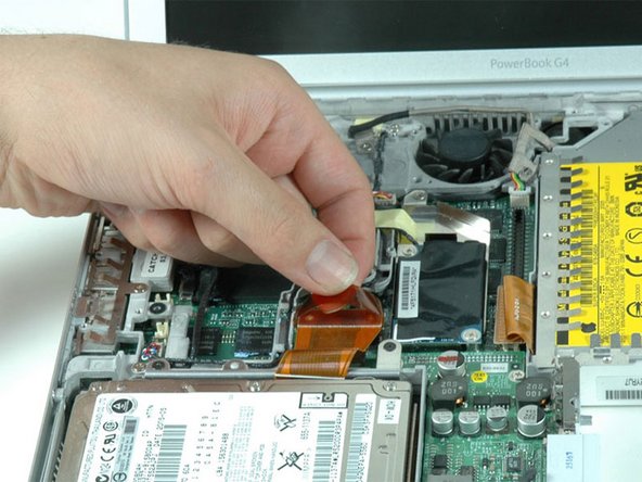
    25. PowerBook G4 Aluminum 12" 1-1.5 GHz Fan Replacement: step 25, image 1 of 1
      • Use the orange plastic loop to disconnect the hard drive cable from the logic board.

      Add Comment

    26. PowerBook G4 Aluminum 12" 1-1.5 GHz Fan Replacement: step 26, image 1 of 1
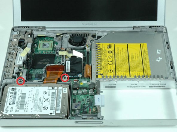
      • Remove the two Phillips screws securing the hard drive bracket to the metal framework.

      Add Comment

    27. PowerBook G4 Aluminum 12" 1-1.5 GHz Fan Replacement: step 27, image 1 of 1
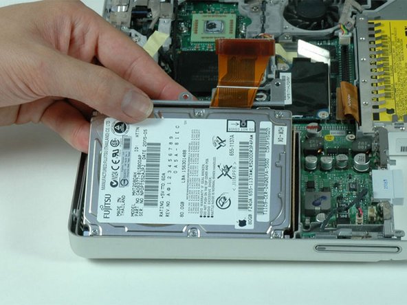
      • Lift the hard drive up and out of the computer.

      Add Comment

    28. PowerBook G4 Aluminum 12" 1-1.5 GHz Fan Replacement: step 28, image 1 of 1
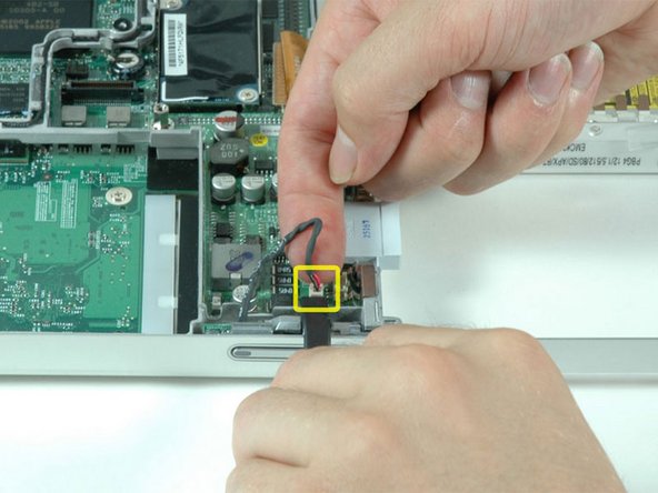
      • Use a spudger or the tip of your finger to disconnect the sleep light cable from the DC-to-DC board.

      Add Comment

    29. PowerBook G4 Aluminum 12" 1-1.5 GHz Fan Replacement: step 29, image 1 of 1
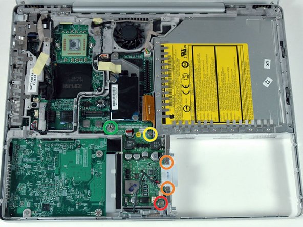
      • Remove the following five secrews/standoffs from the DC-to-DC board:

      • One 3 mm Phillips in the lower right corner.

      • Two 3.5 mm Phillips on either side of the battery contacts.

      • One 10 mm Phillips in the upper right corner.

      • One 14 mm long 4 mm standoff in the upper left corner. You can remove this standoff either with a 4 mm nut driver or needlenose pliers.

      Add Comment

    30. PowerBook G4 Aluminum 12" 1-1.5 GHz Fan Replacement: step 30, image 1 of 1
      • Remove the silver EMI fingers located near the battery contacts.

      Add Comment

    31. PowerBook G4 Aluminum 12" 1-1.5 GHz Fan Replacement: step 31, image 1 of 1
      • Use a spudger to pry up the end of the DC-to-DC board closest to the display and remove the board from the computer.

      Add Comment

    32. PowerBook G4 Aluminum 12" 1-1.5 GHz Fan Replacement: step 32, image 1 of 1
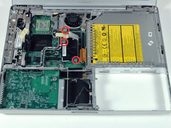
      • Remove the three Phillips screws securing the modem and modem shield to the logic board.

      Add Comment

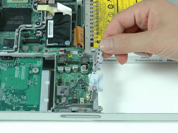
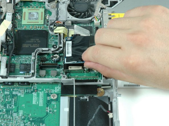
    33. PowerBook G4 Aluminum 12" 1-1.5 GHz Fan Replacement: step 33, image 1 of 1
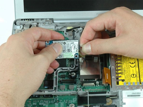
      • Disconnect the modem from the logic board by lifting the bottom edge of the modem. Don't remove the modem entirely just yet as it is still connected to the RJ-11 board.

      Add Comment

    34. PowerBook G4 Aluminum 12" 1-1.5 GHz Fan Replacement: step 34, image 1 of 1
      • Turn the modem over and disconnect the RJ-11 cable.

      Add Comment

    35. PowerBook G4 Aluminum 12" 1-1.5 GHz Fan Replacement: step 35, image 1 of 1
      • The connectors at the ends of the cables are often attached very firmly to the sockets on the logic board. Pulling directly on the cable will either separate the cable from its connector or the socket from the logic board.

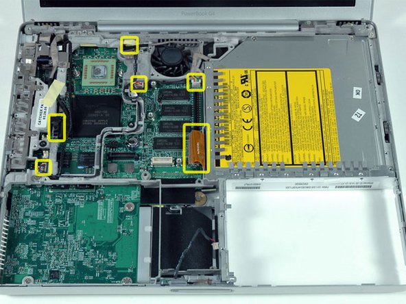
      • Carefully disconnect six indicated connectors from the logic board. To disconnect the four white connectors, use your fingernails or a dental pick to carefully pry the connectors from their sockets. Make sure you're pulling only on the connector and not on the socket.

      Add Comment

    36. PowerBook G4 Aluminum 12" 1-1.5 GHz Fan Replacement: step 36, image 1 of 1
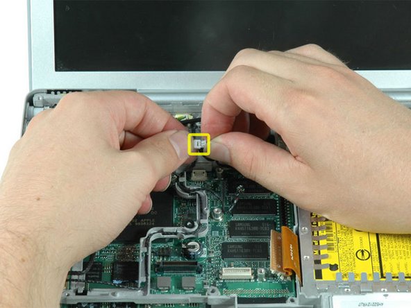
      • Lift up microphone cable from the lower left corner of the fan, and disconnect the two sections of the cable.

      Add Comment

    37. PowerBook G4 Aluminum 12" 1-1.5 GHz Fan Replacement: step 37, image 1 of 1
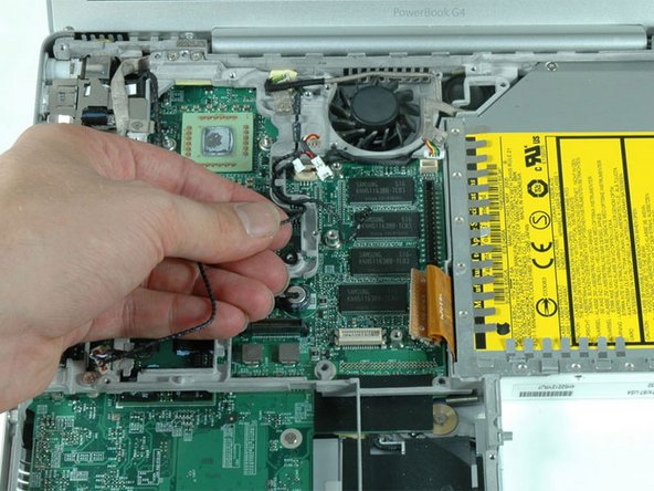
      • Deroute the microphone cable from its channel in the metal framework.

      Add Comment

    38. PowerBook G4 Aluminum 12" 1-1.5 GHz Fan Replacement: step 38, image 1 of 1
      • Remove the following nine screws:

      • Four 3 mm Phillips allong the left edge and near the fan.

      • One 4 mm Phillips in the bottom left corner.

      • Two 6 mm Phillips near the left hinge.

      • One 9 mm Phillips in the top left corner of the fan.

      • One 12 mm Phillips just above where the hard drive was located.

      Add Comment

    39. PowerBook G4 Aluminum 12" 1-1.5 GHz Fan Replacement: step 39, image 1 of 1
      • Peel up the yellow tape securing the display data cable to the metal framework, and deroute the display data cable from its slot in the framework.

      Add Comment

    40. PowerBook G4 Aluminum 12" 1-1.5 GHz Fan Replacement: step 40, image 1 of 1
      • Remove the newly revealed Phillips screw near the RJ-11 board.

      • Some computers may have two Phillips screws securing the RJ-11 board to the metal framework.

      Add Comment

    41. PowerBook G4 Aluminum 12" 1-1.5 GHz Fan Replacement: step 41, image 1 of 1
      • Lift the RJ-11 board up from the left side, and remove the single Phillips screw hidden beneath.

      Add Comment

    42. PowerBook G4 Aluminum 12" 1-1.5 GHz Fan Replacement: step 42, image 1 of 1
      • Lift up and remove the silver EMI fingers located above the ports on the left side of the computer.

      Add Comment

    43. PowerBook G4 Aluminum 12" 1-1.5 GHz Fan Replacement: step 43, image 1 of 1
      • Pull back on the orange optical drive cable with one hand, and use your other hand to lift the front section of the metal framework over the optical drive cable.

      Add Comment

    44. PowerBook G4 Aluminum 12" 1-1.5 GHz Fan Replacement: step 44, image 1 of 1
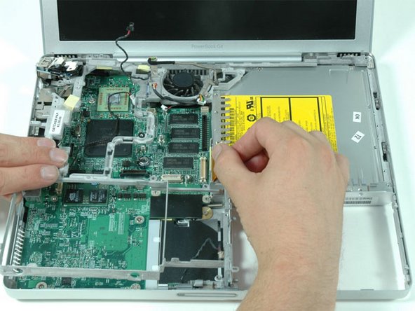
      • Deroute the microphone cable from its channel in the upper right corner of the framework.

      • The metal framework should now be free can be removed from the computer. Be careful when removing the metal framework that none of the cables get caught on the framework.

      Add Comment

    45. PowerBook G4 Aluminum 12" 1-1.5 GHz Fan Replacement: step 45, image 1 of 1
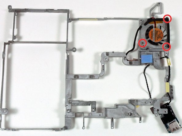
      • Turn the metal framework over and remove the three Phillips screws securing the fan to framework.

      Add Comment

    46. PowerBook G4 Aluminum 12" 1-1.5 GHz Fan Replacement: step 46, image 1 of 1
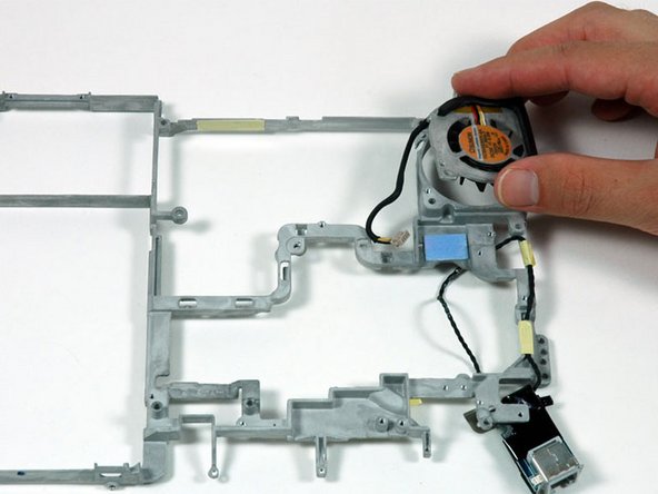
      • Lift the fan off the metal framework.

      Add Comment

Conclusion

To reassemble your device, follow these instructions in reverse order.

Cancel: I did not complete this guide.

System

Member since: 09/24/09

2,562 Guides authored

0 Guide Comments

Add Comment

View Statistics:

Past 24 Hours: 0

Past 7 Days: 0

Past 30 Days: 0

All Time: 9