
Introduction
Use this guide to save money by replacing only the LCD, not the entire display.
What you need
-
-
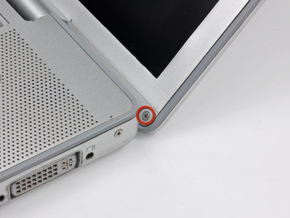
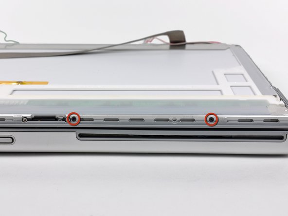
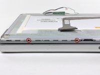
Remove the two 6.3 mm Phillips screws near the lower left and right corners of the display.
-
-
-
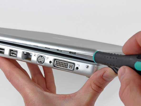
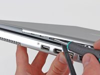
Insert the flat end of a spudger between the rear display bezel and the plastic rim attached to the front display bezel near the lower right corner of the display.
-
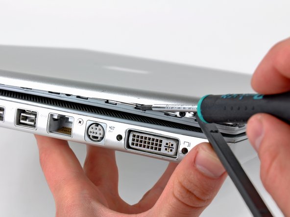
While carefully prying the rear display bezel away from the display assembly, use a small flathead screwdriver to pry the small steel clip nearest the bottom right corner of the display away from the edge of the front display bezel.
-
Repeat the above procedure until you've released all the clips along the right side of the display.
-
-
-
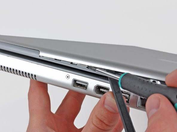
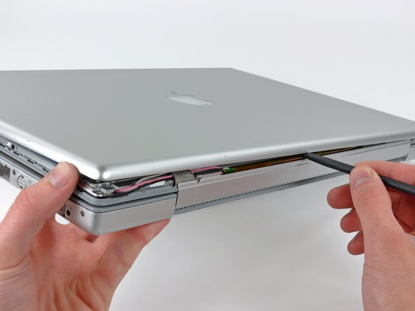
Slightly lift the recently-freed corner of the rear display bezel to separate the clips with a spudger along the span of the clutch hinges.
-
-
-
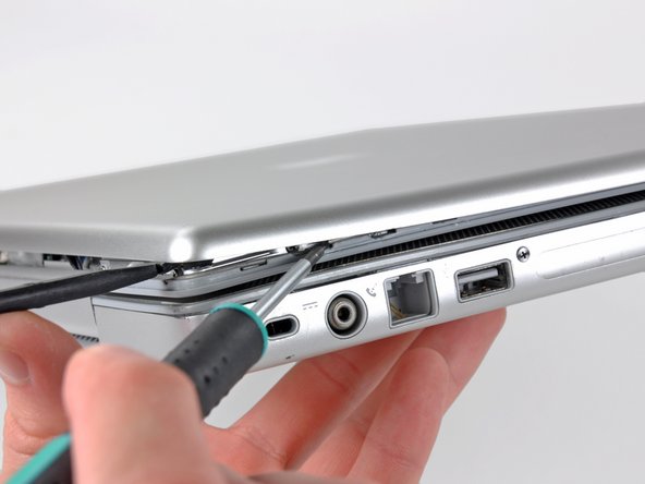
Insert the flat end of a spudger between the rear display bezel and the plastic surround of the front display bezel near the lower left corner of the display.
-
Carefully pry the rear display bezel away from the front display bezel to expose the metal clips along the left side of the display.
-
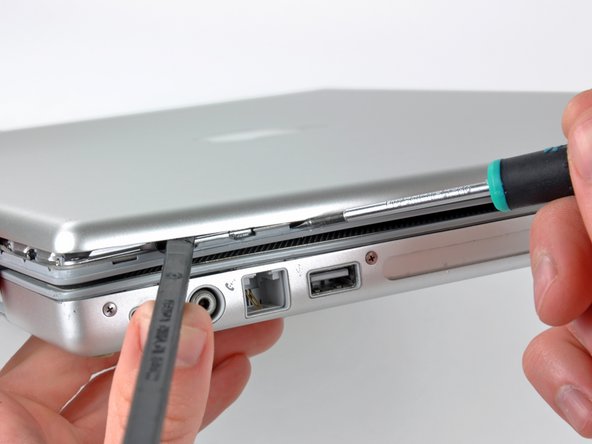
Repeat the previous procedure to release the clips along the left side of the rear display bezel.
-
-
-
Slightly lift the lower edge of the rear display bezel and push it toward the top edge of the display, releasing the clips along the top edge of the rear display bezel.
-
Remove the rear display bezel and set it aside.
-
-
-
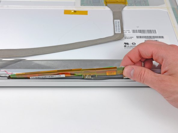
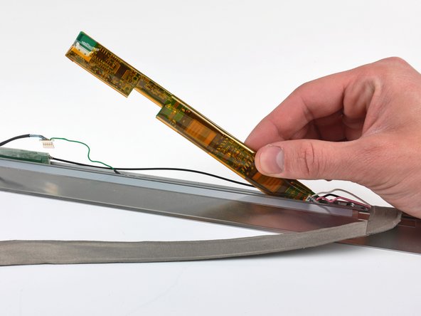
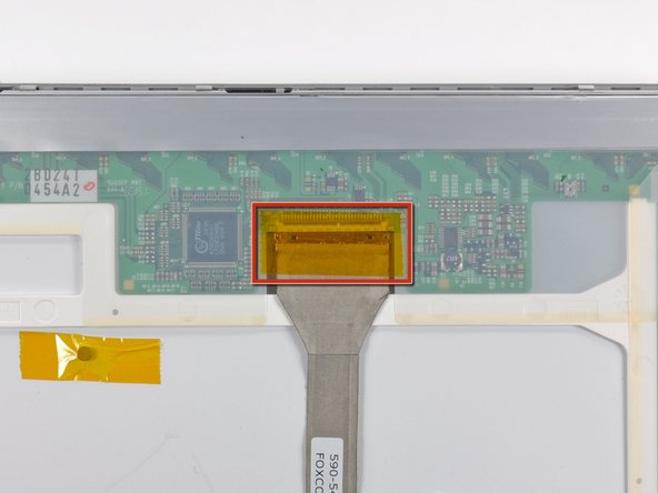
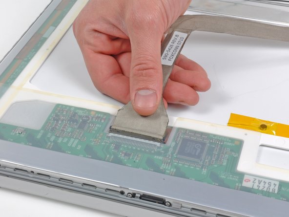
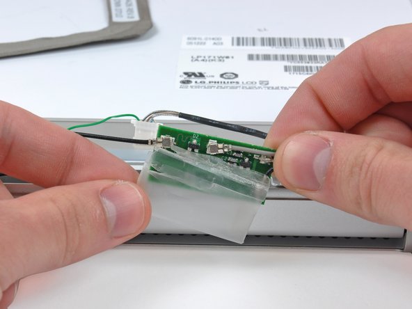
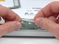
Carefully lift the display inverter board from the side nearest the display data cable connector.
-
-
-
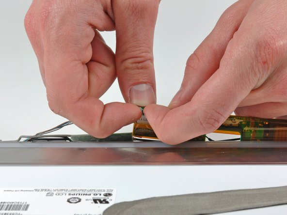
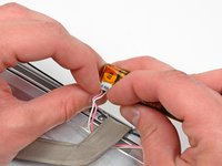
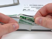
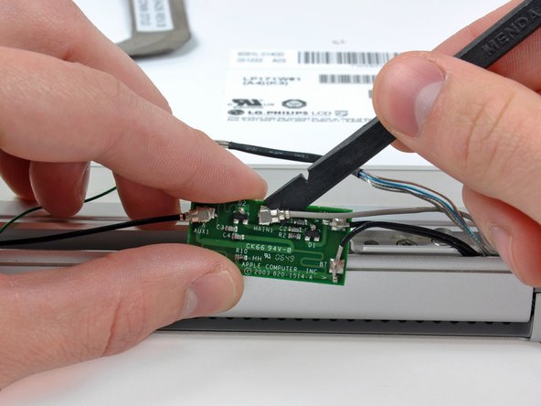
Use your fingernails to pull the ears on both sides of the inverter cable connector away from its socket on the inverter board.
-
-
-
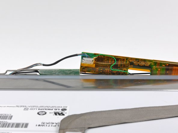
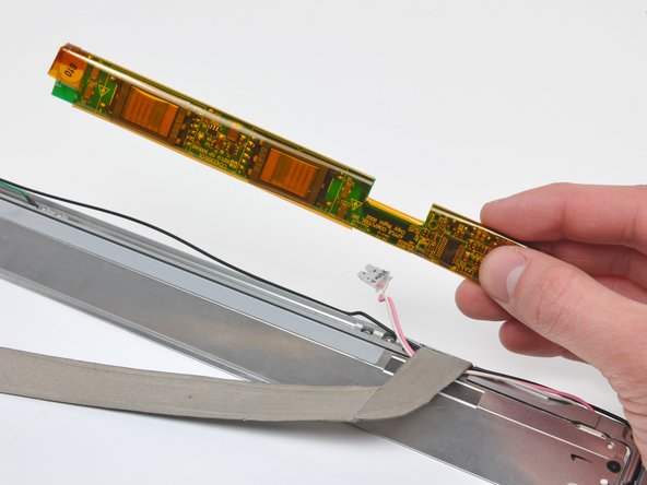
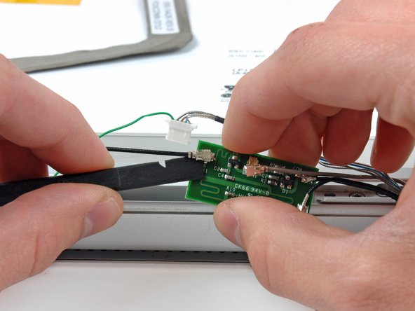
Use your fingers to pull the backlight connector away from its socket on the inverter board.
-
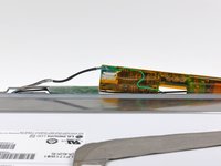
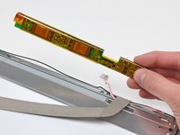
Remove the display inverter from the display assembly.
-
-
-
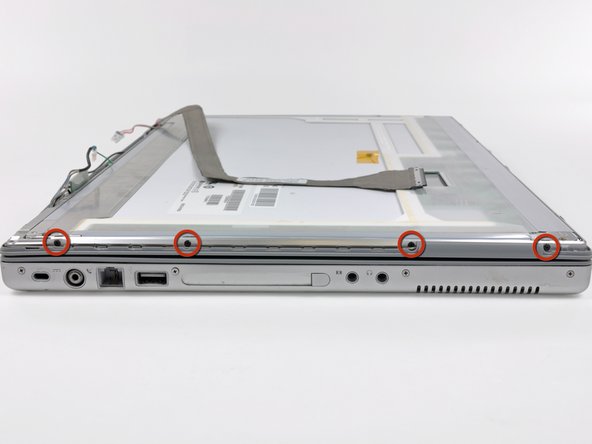
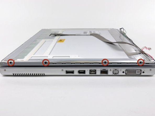
Remove the four 3.2 mm Phillips screws securing the left side of the LCD assembly to the front display bezel.
-
-
-
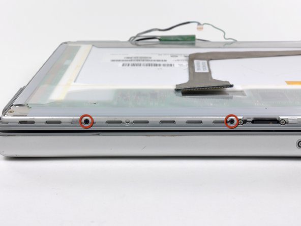
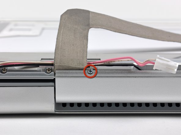
Remove the single 2.5 mm Phillips screw securing the display data cable ground loop to the front display bezel.
-
-
-
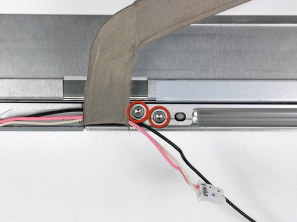
Remove the two 10.3 mm T8 Torx screws securing the left side of the clutch hinges to the front bezel.
-
-
-
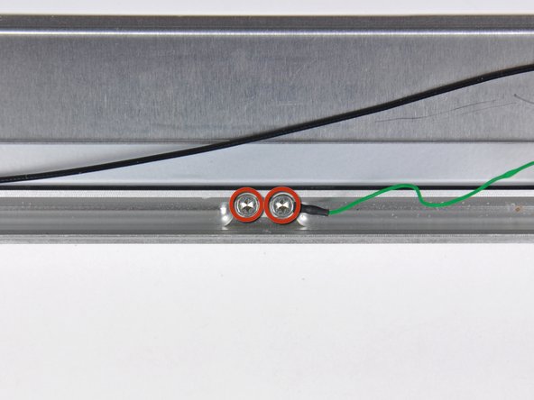
Remove the two 10.3 mm T8 Torx screws securing the center of the clutch hinges to the front bezel.
-
-
-
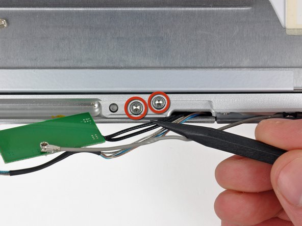
Remove the two 10.3 mm T8 Torx screws securing the right side of the clutch hinges to the front display bezel.
-
-
-
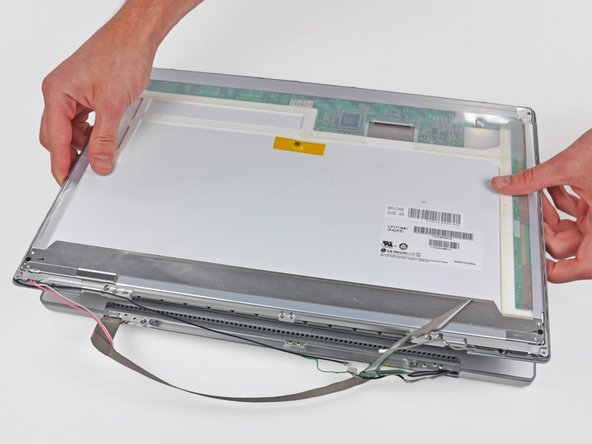
Press the display release button to release the top edge of the display from the upper case.
-
Carefully wiggle and lift the display assembly straight up off its positioning pins on the clutch hinges.
-
-
-
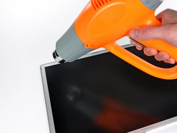
With the heat gun set to low, start by heating the front display bezel near the upper left corner of the display panel.
-
-
-
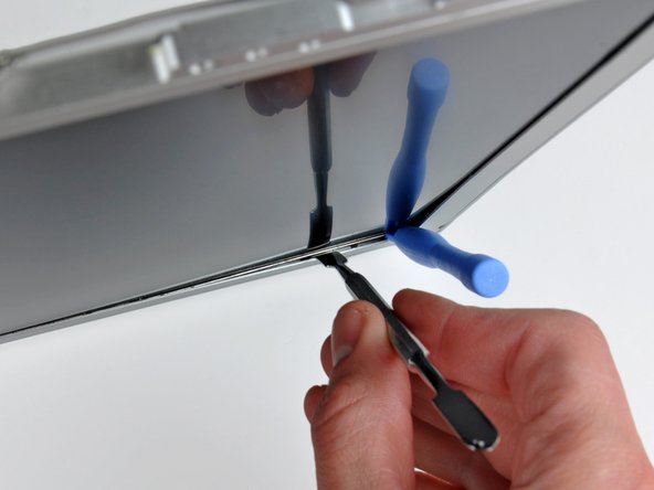
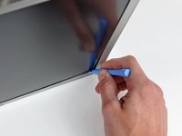
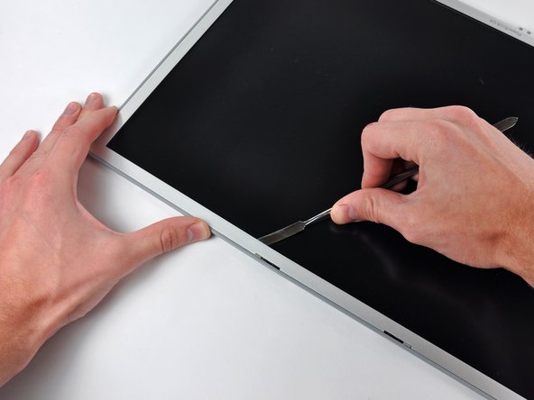
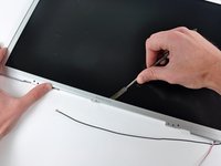
Insert a plastic opening tool between the metal LCD frame and the front bezel.
-
Use the flat end of a metal spudger to gently pry up the adhesive securing the metal LCD frame to the front bezel, taking special care not to scratch the LCD panel.
-
-
-
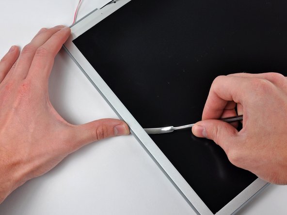
While it is still inserted between the metal LCD frame and the front bezel, run the edge of your metal spudger along the top edge of the display to separate the adhesive securing the two pieces together, heating the area you are working on with a heat gun as necessary.
-
-
-
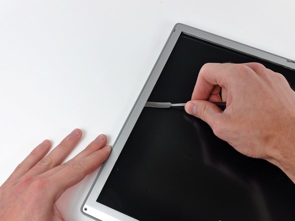
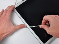
Continue running the edge of your metal spudger between the LCD frame and the front bezel until the right, bottom, and left sides of the LCD are free.
-
-
-
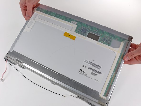
Lift the LCD out of the front display bezel, using your metal spudger to release any adhesive if necessary.
-
-
-
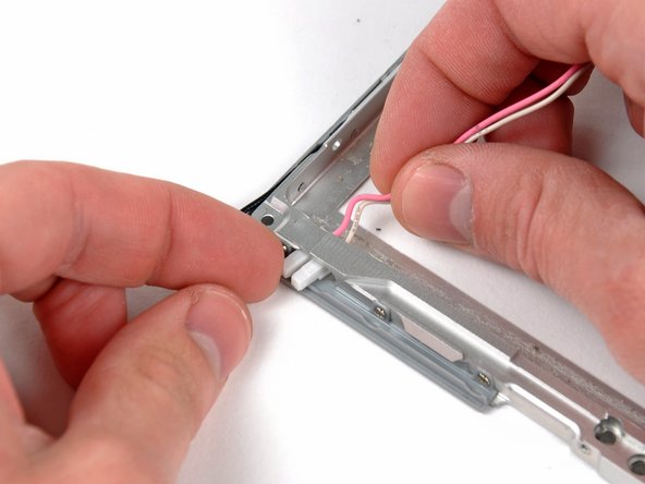
With the LCD partially removed from the front bezel, carefully push the backlight connector through its tunnel in the front bezel.
-


To reassemble your device, follow these instructions in reverse order.
