
Introduction
Replacing your lower case requires removing nearly every component from your PowerBook.
What you need
-
-
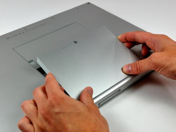
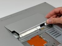
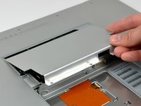
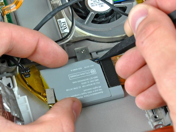
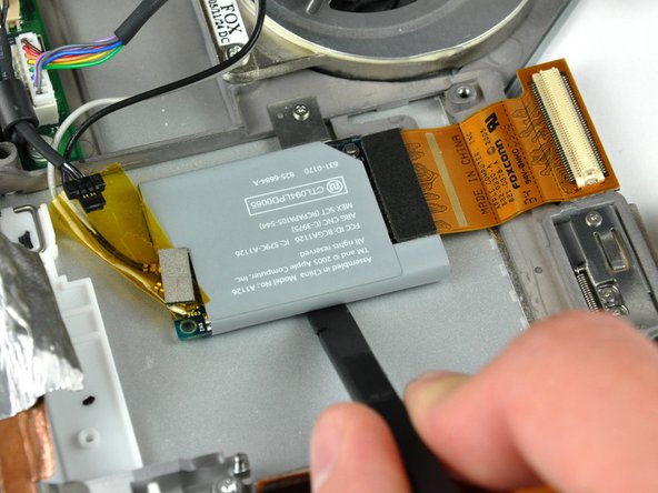
Use your thumbs to push the two battery retaining tabs away from the battery.
-
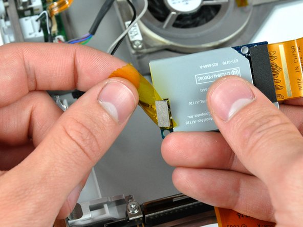
The battery should pop up enough to rotate it toward yourself and lift it out of the lower case.
-
-
-
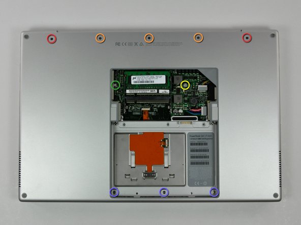
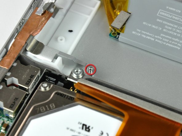
Remove the following ten screws:
-
Two 14.7 mm shouldered Phillips.
-
Three 12.3 mm Phillips.
-
One 3.8 mm T8 Torx.
-
One 6.8 mm T8 Torx.
-
Three 1.3 mm Phillips.
-
-
-
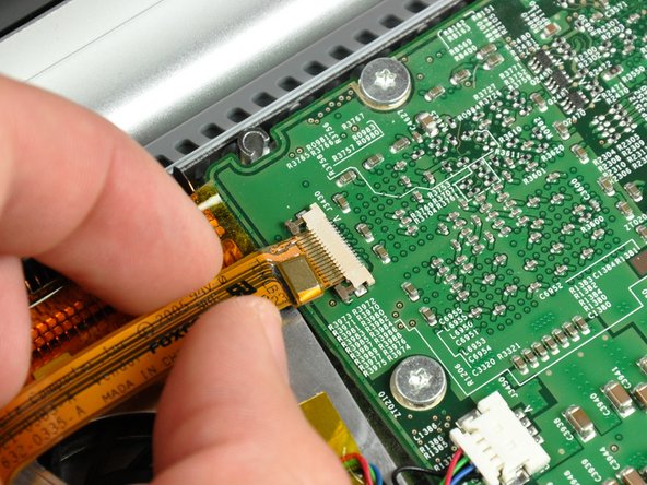
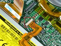
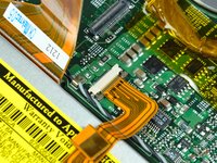
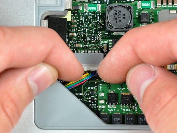
Use your fingernails to separate the ZIF cable lock away from its socket. (Move the two brown bits down 1mm)
-
-
-
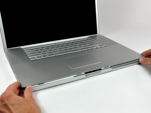
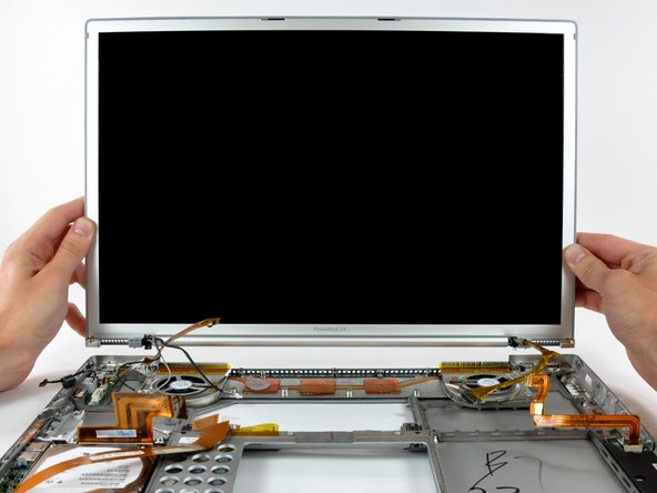
Starting near the display, lift the upper case straight up off the lower case, minding any cables that may get caught.
-
-
-
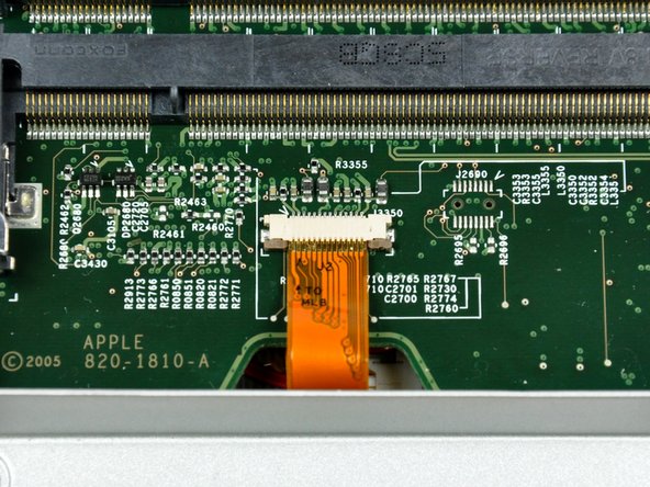
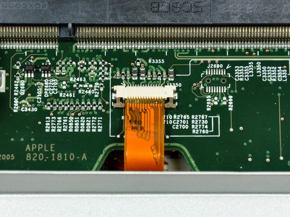
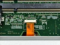
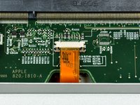
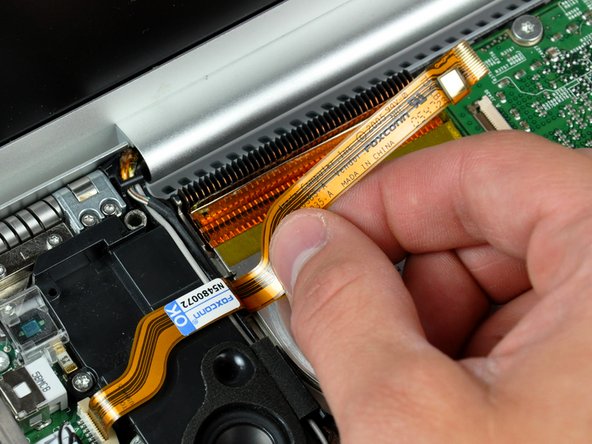
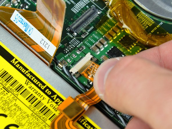
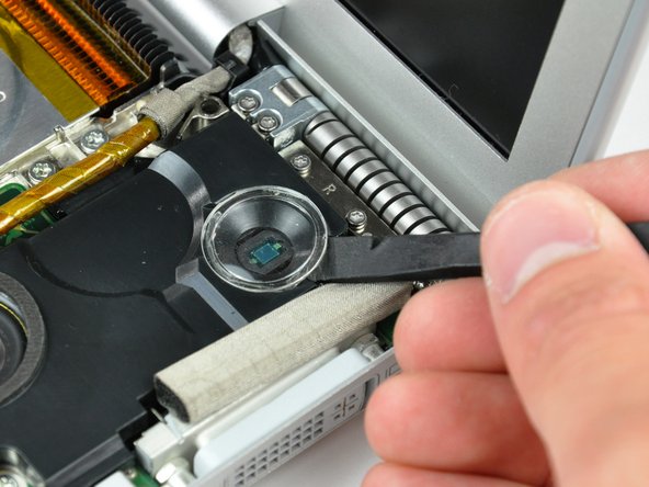
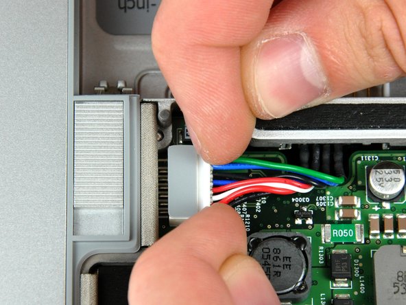
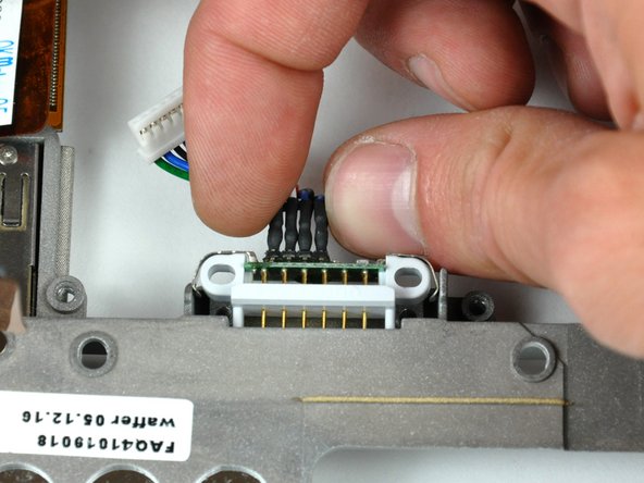
Use your fingernails or the tip of a spudger to separate the ZIF cable lock from its socket.
-
-
-
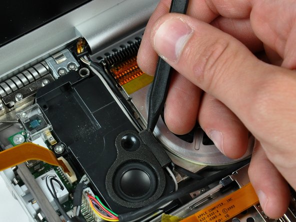
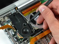
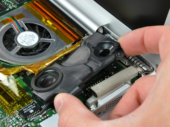
If necessary, use the tip of a spudger to remove the small piece of foam tape from the side of the left speaker.
-
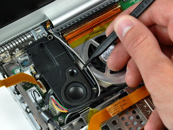
De-route the AirPort antenna cables from the channel in the left speaker.
-
-
-
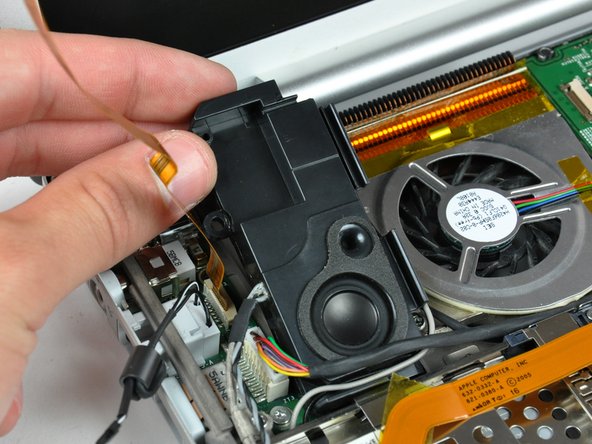
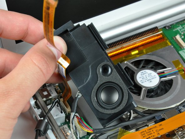
Lift the left speaker from its rear edge and maneuver it out of the lower case, minding the cables sitting in the channel near the front edge of the left speaker.
-
-
-
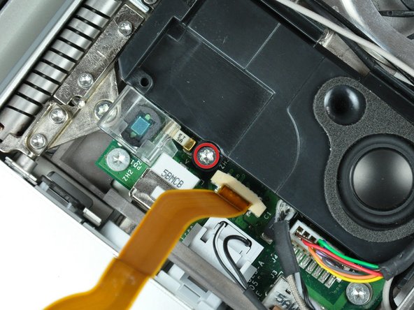
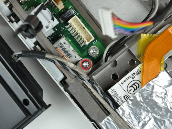
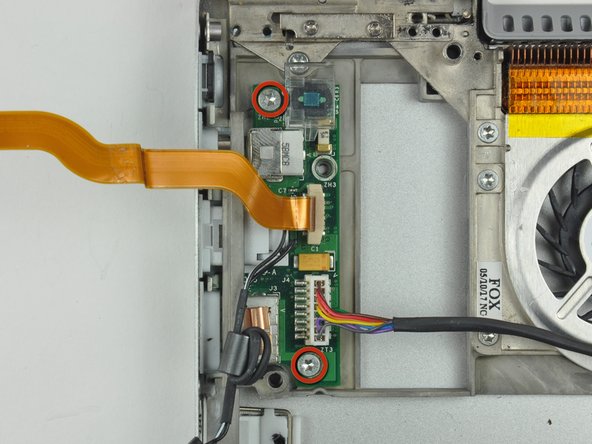
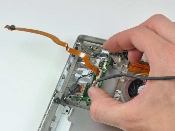
Remove the single 6.9 mm T8 Torx screw securing the speaker cable ground loop to the lower case.
-
-
-
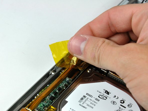
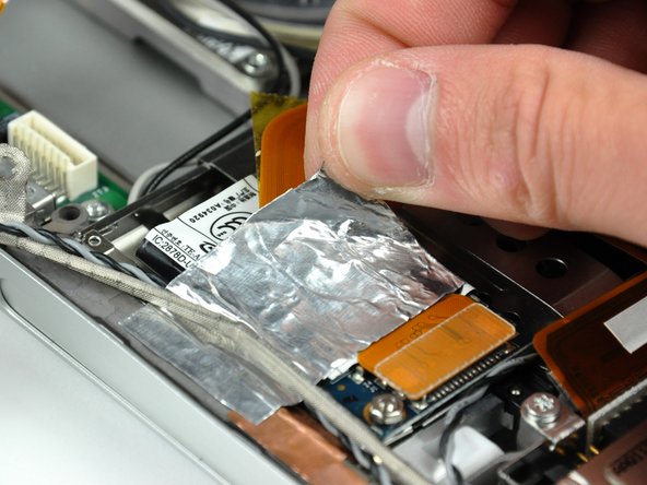
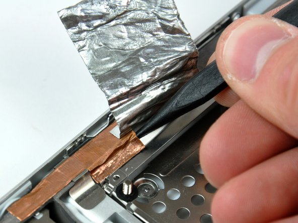
Peel back the piece of foil tape covering the modem cable to free the speaker cable held underneath.
-
-
-
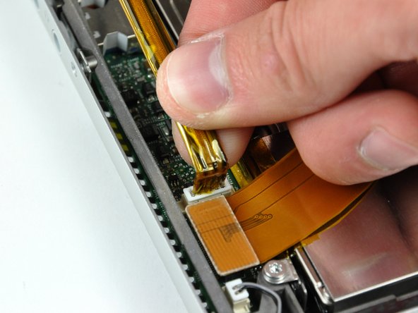
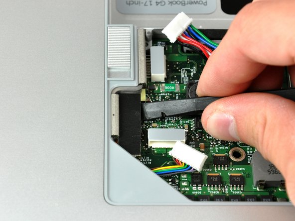
Use the flat end of a spudger to pry the hard drive ribbon cable connector up off the logic board.
-
-
-
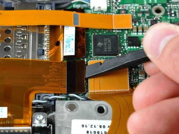
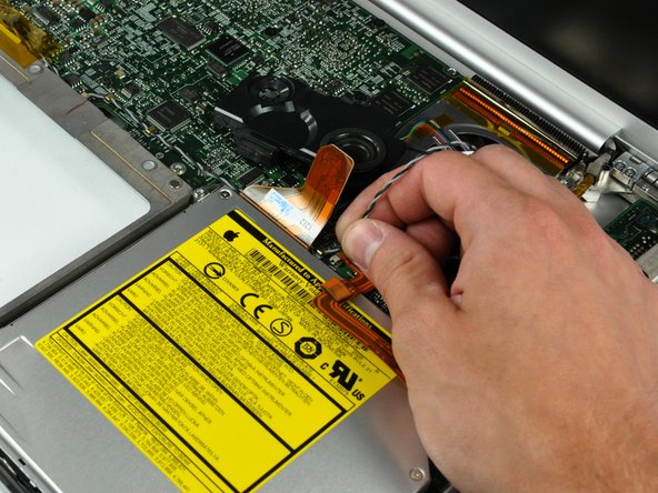
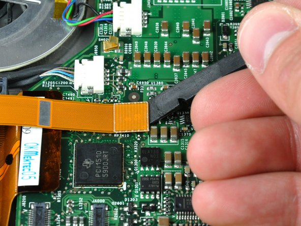
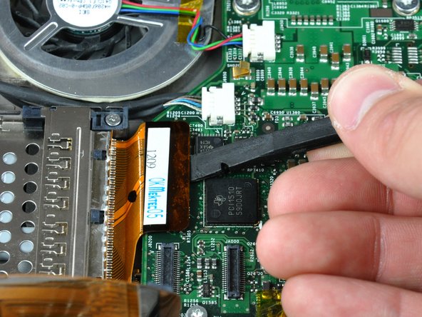
Use the flat end of a spudger to pry the optical drive cable connector up off the logic board.
-
-
-
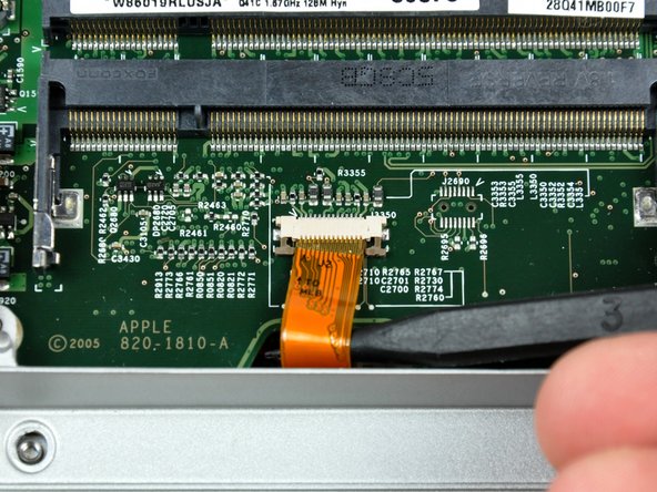
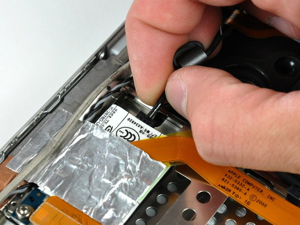
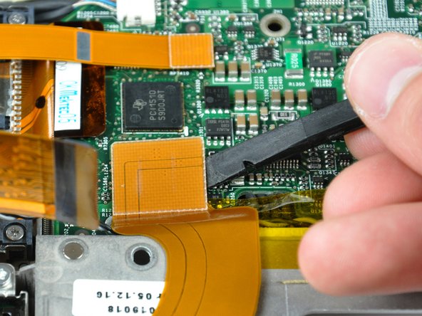
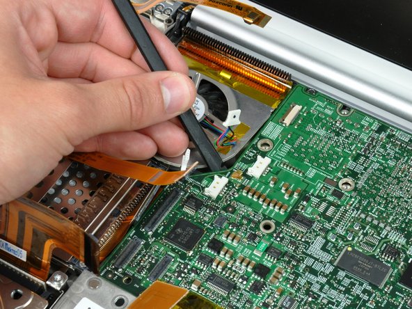
Use your fingernails or the tip of a spudger to separate the ZIF cable lock from its socket.
-
-
-
Close your PowerBook, minding any cables that may interfere, and flip it over.
-
Disconnect the power cable connector by pulling it straight away from its socket on the logic board.
-
-
-
Use the flat end of a spudger to pry the AirPort/Bluetooth cable connector up off the logic board.
-
-
-
Use the flat end of a spudger to pry the PC card cage cable connector up off the logic board.
-
-
-
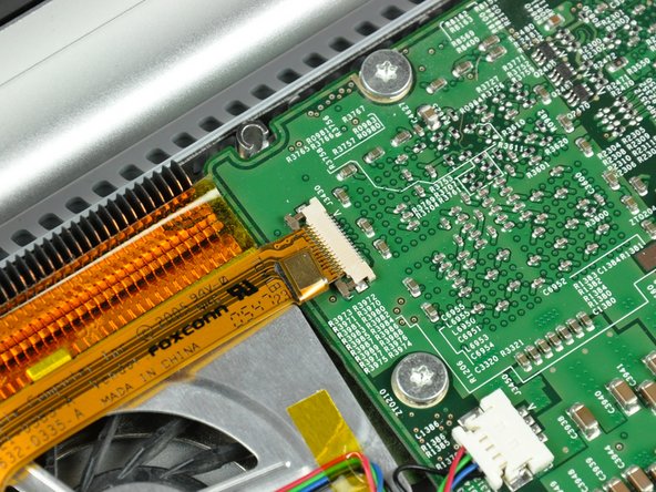
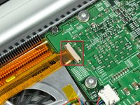
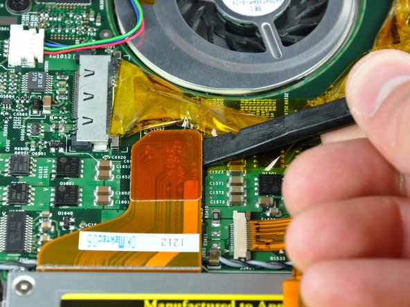
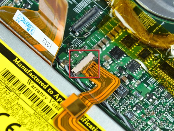
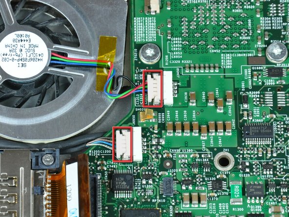
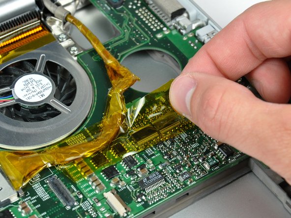
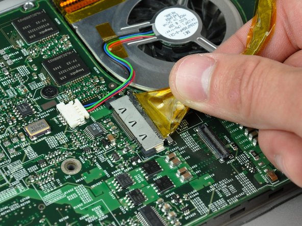
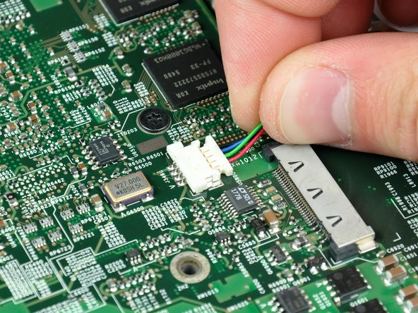
Disconnect both of the following connectors from the logic board:
-
Left fan cable.
-
Inverter cable.
-
-
-
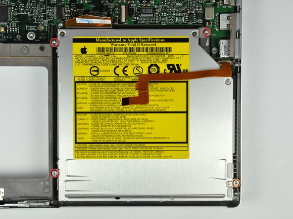
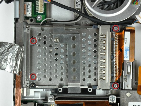
Remove the following four screws securing the optical drive to the lower case:
-
Three 6.8 mm T8 Torx.
-
One 3.8 mm T8 Torx.
-
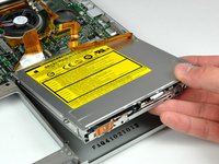
Lift the optical drive out of the lower case, minding any cables that may get caught.
-
-
-
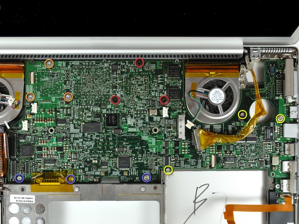
Remove the following 12 screws:
-
Three black 5.7 mm T8 Torx.
-
Three 7 mm T8 Torx with spring washers.
-
Three 6.8 mm T8 Torx.
-
Three 3.8 mm T8 Torx.
-
-
-
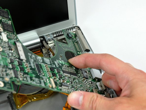
If necessary, use a spudger to pry up the left edge of the logic board to separate the solidified thermal paste from the heat sink.
-
-
-
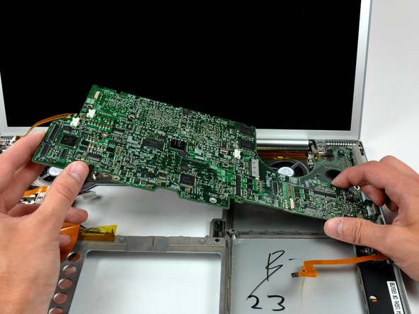
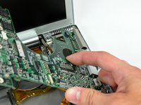
Lift the logic board from its left edge and rotate it toward the right side of the lower case.
-
Rotate the logic board until it is nearly vertical, and wiggle it around until it releases from the lower case.
-
-
-
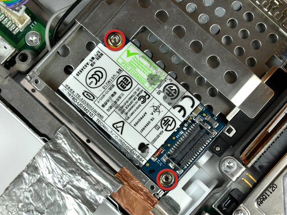
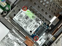
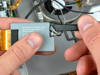
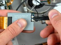
Use a 4 mm nut driver to remove the two nuts securing the modem to the PC card cage.
-
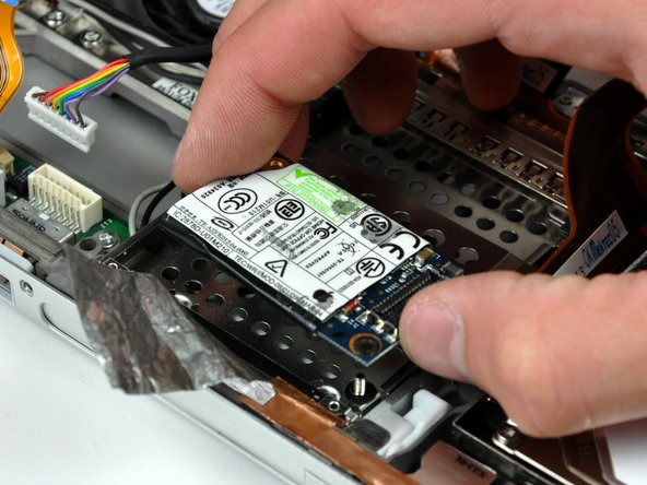
Lift the modem straight up off the studs on the PC card cage.
-
-
-
Use the tip of a spudger to peel back the small strip of copper tape off the edge of the PC card cage near the side of the lower case.
-
-
-
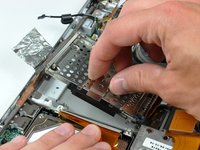
Remove the four Phillips screws securing the PC card cage to the lower case.
-
Lift the PC card cage by its center piece and maneuver it out of the lower case.
-
-
-
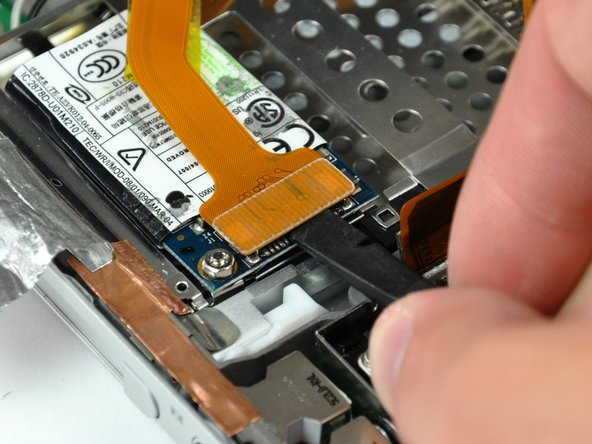
Use the tip of a spudger to press the metal pressure connector down through the hole in the AirPort/Bluetooth board and lift it out from the lower case.
-
-
-
Use the flat end of a spudger to pry the AirPort/Bluetooth board off the adhesive securing it to the lower case.
-
-
-
If necessary, remove the piece of tape and EMI foam covering the AirPort/Bluetooth antennas.
-
-
-
Use the flat end of a spudger to pry both antenna connectors off the AirPort/Bluetooth board.
-
-
-
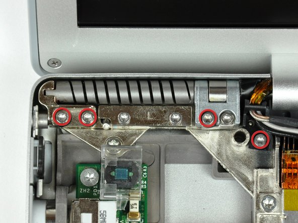
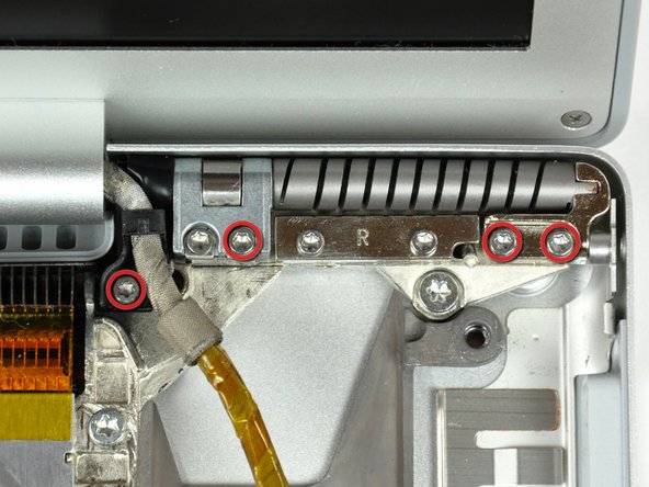
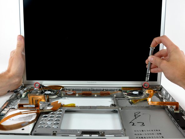
While supporting the display with one hand, remove the last two T6 Torx screws from the display hinges.
-
-
-
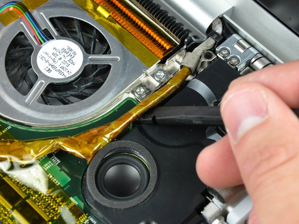
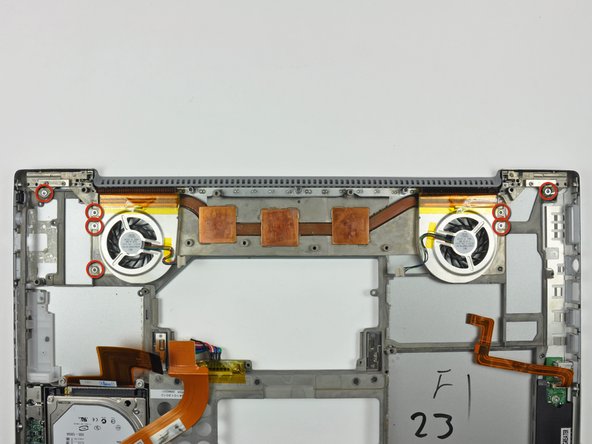
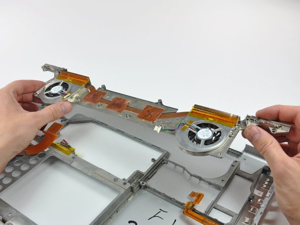
Lift the heat sink and fan assembly out of the lower case.
-
Lift the heat sink and fan assembly out of the lower case.
-
-
-
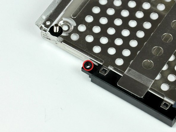
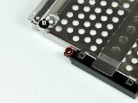
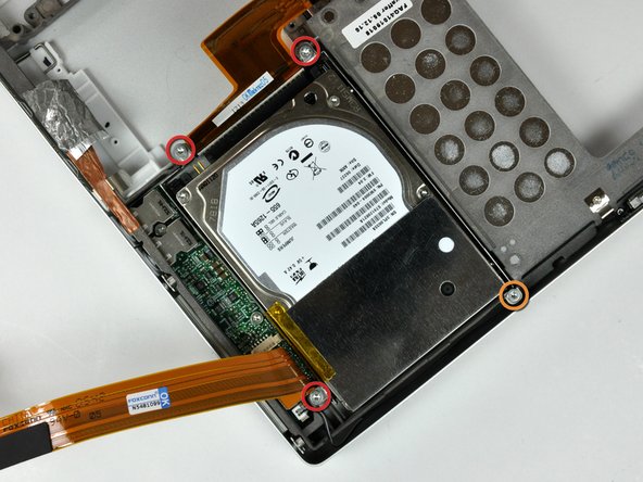
Remove the following four screws:
-
Three 11.1 mm T8 Torx.
-
One 3.9 mm T8 Torx.
-
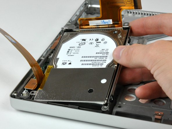
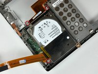
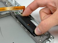
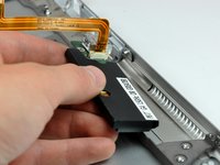
Lift the hard drive out of the lower case.
-
-
-
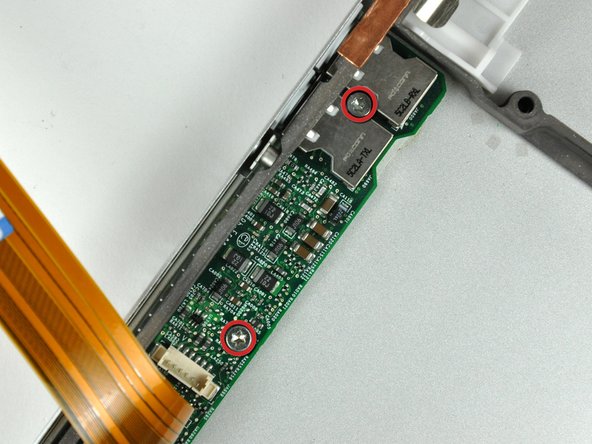
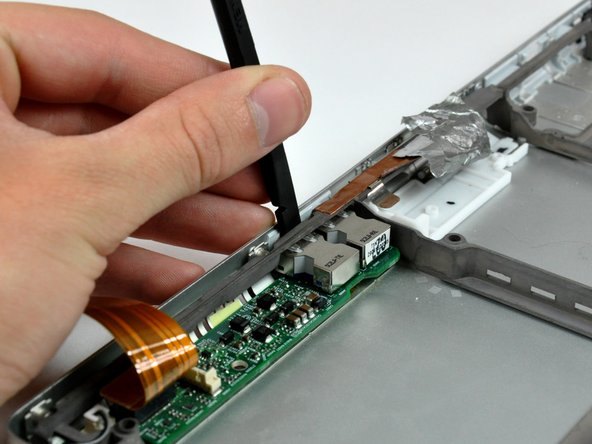
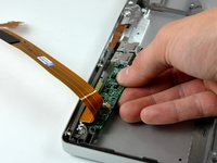
Use the flat end of a spudger to pry the USB sockets away from the left edge of the lower case.
-
-
-
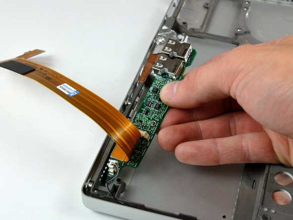
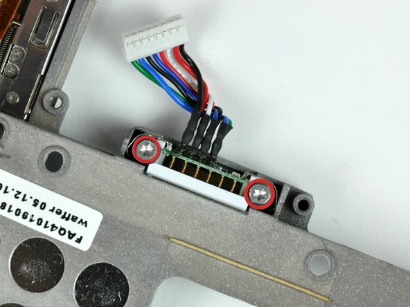
Lift the sound card slightly out of the lower case, minding the fragile lower portion holding the microphone connector.
-
-
-
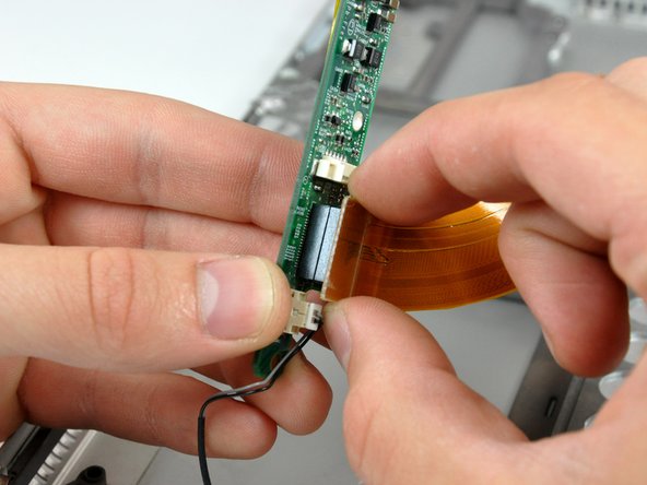
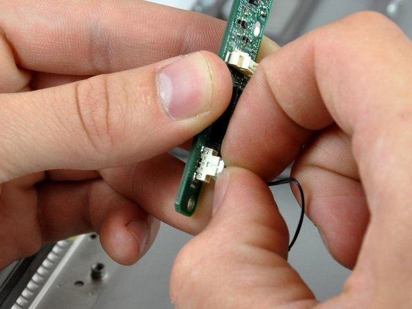
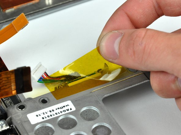
Use your fingernails to pull the microphone connector straight away from its socket on the sound card.
-
-
-
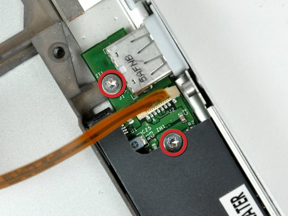
Pull the board away from the side of the lower case to separate the USB socket from the bezel on the lower case.
-
Lift the PRAM battery & USB board out of the lower case.
-


To reassemble your device, follow these instructions in reverse order.
