
Introduction
Use this guide for information on installing a new logic board or re-install the old one. Removing the logic board requires 17 desolders to remove the old logic board. To install a new logic board, then 17 resolders need to be done. Unless you feel very confident in your soldering abilities, you could end up disassembling the the logic board and not be able to reassemble it. Also, be careful when handling the camera after taking the casing off because the camera's capacitor for the flash can shock you. Use this guide to gain access to and replace the logic board.
What you need
-
-
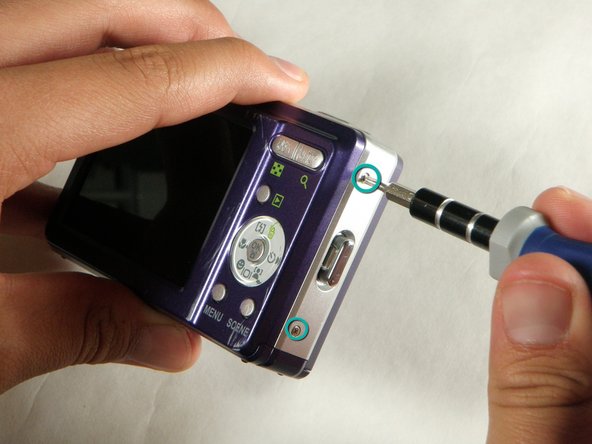
Unscrew 6 Phillips screws using the #00 Phillips screwdriver.
-
Two screws are on the left side of the camera.
-
Two screws are on the right side of the camera.
-
Two screws are on the bottom of the camera.
-
-
-
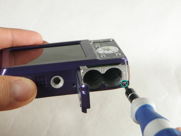
Open battery slot on the bottom of the camera by sliding the door to the right.
-
Remove the 4 mm phillips screw on the bottom right using the #00 phillips screwdriver.
-
-
-
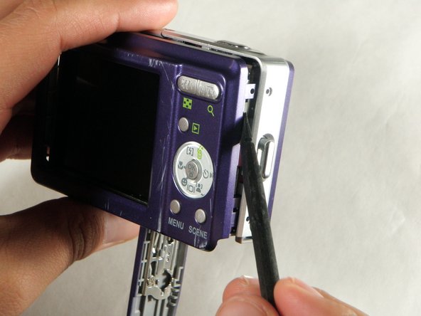
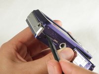
Insert spudger in the seam at the bottom of the camera.
-
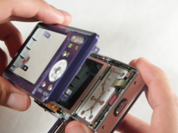
Gently separate the rear case from the front of the camera.
-
-
-
Using the #00 phillips screwdriver remove the screw attached to the front casing in the top left corner. Front case should easily separate.
-
-
-
Using the #00 phillips screwdriver remove the screw on the inside of the battery door.
-
Slide the battery door off of the hinge.
-
-
-
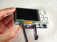
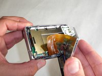
Using the spudger gently lift up the LCD screen carefully to keep the ribbon intact.
-
Place the LCD screen on a non-abrasive surface.
-
-
-
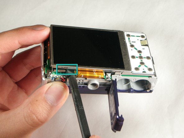
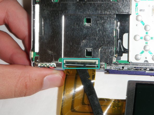
Using the spudger lift the black flap up to release the ribbon.
-
The LCD screen will now be completely detached from the camera.
-
-
-
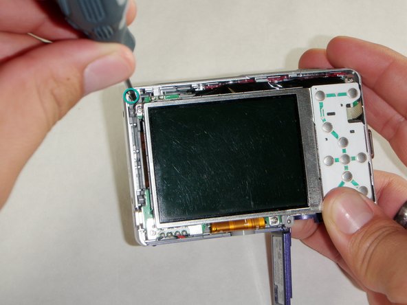
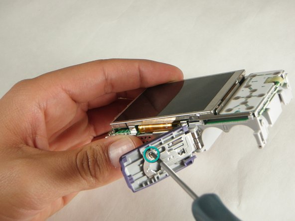
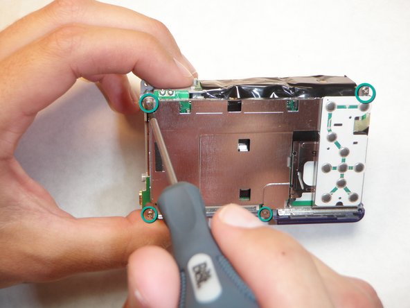
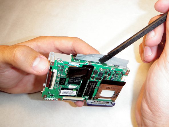
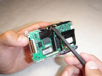
Using the #00 phillips screwdriver remove the four screws on the outer edge of the LCD holding plate.
-
-
-
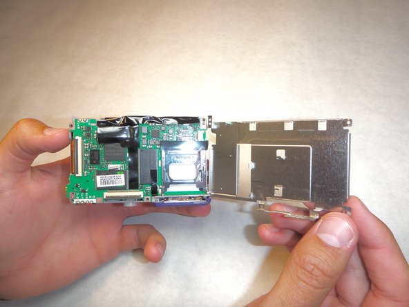
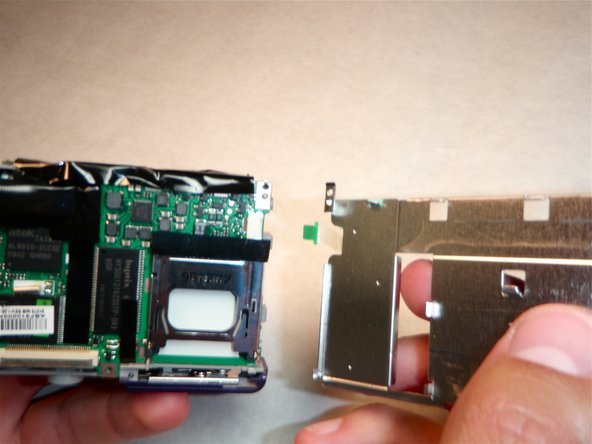
Using your right hand grab the left side of the LCD holding plate and rotate it to the right.
-
-
-
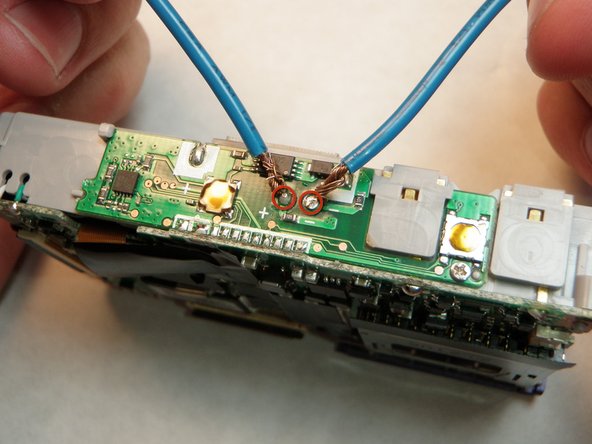
Click the link below for instructions on how to make the capacitor discharge tool: Nintendo DSi XL Camera Ribbon Replacement
-
Keep the wires connected to the capacitor terminals for 2 minutes to completely discharge the capacitor
-
The camera should be completely safe to handle now.
-
-
-
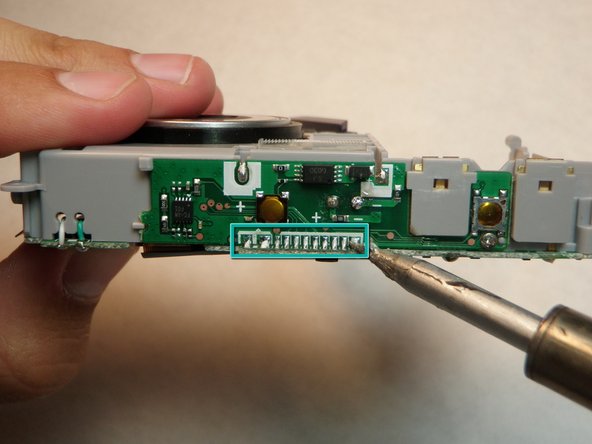
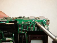
Touch the hot tip of the solding iron to the first solder connecting the flash mechanism to the logic board until the solder melts.
-
Repeat this for the next 10 solders.
-
Verify solders have detached logic board.
-
-
-
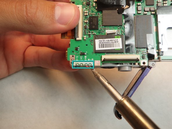
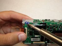
Touch the hot soldering iron to the solder in the lower left corner connecting the logic board to the red wire.
-
When the solder has completely melted, gently pull the wire free from the logic board.
-
Repeat for the red, blue, and then black wires.
-
-
-
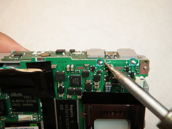
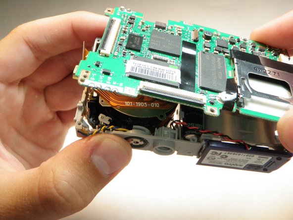
Touch the soldering iron tip to the solder in the upper right corner connecting the logic board to the battery lead.
-
Pull the battery lead out of the slot in the logic board. This must be done immeadiately after the solder melts.
-
Repeat for the solder to the left.
-
The logic board will now be completely free from the camera.
-
-
-
insert the battery leads into the slots in the new logic board.
-
Solder both leads to the logic board.
-


To reassemble your device, follow these instructions in reverse order.
