/

iMac G5 20" Model A1076 Logic Board Replacement

What you need

  1. iMac G5 20" Model A1076 Logic Board Replacement, iMac G5 20" Model A1076 Logic Board Replacement: step 1, image 1 of 1
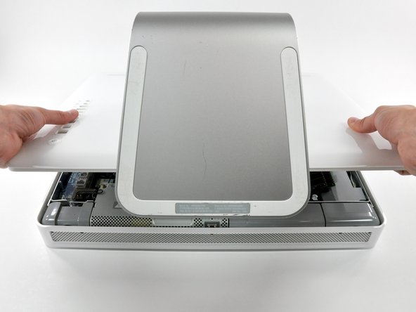
    • Lay the iMac display-side down on a flat surface.

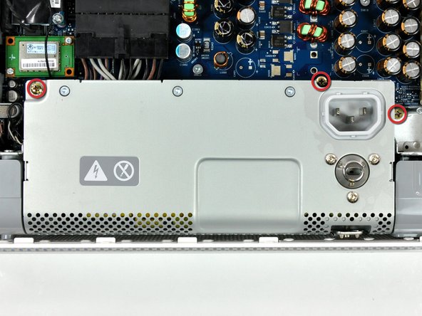
    • Loosen the three Phillips screws securing the rear panel to the iMac.

    • These screws are captive in the iMac. The center screw will stop turning after about 3.5 turns and the outer screws will stop turning after about 5.5 turns. Do not try to remove these screws from your iMac.

  2. iMac G5 20" Model A1076 Logic Board Replacement: step 2, image 1 of 2 iMac G5 20" Model A1076 Logic Board Replacement: step 2, image 2 of 2
    • Lift the rear panel slightly near the bottom of the iMac.

    • Pull the rear panel toward yourself and remove it from the iMac.

  3. iMac G5 20" Model A1076 Logic Board Replacement: step 3, image 1 of 1
    • Remove the three Phillips screws securing the power supply to the chassis.

    • The two leftmost screws are captive in the power supply.

    • To aid in removal, it may be helpful to lift the center screw slightly away from the midplane.

  4. iMac G5 20" Model A1076 Logic Board Replacement: step 4, image 1 of 2 iMac G5 20" Model A1076 Logic Board Replacement: step 4, image 2 of 2
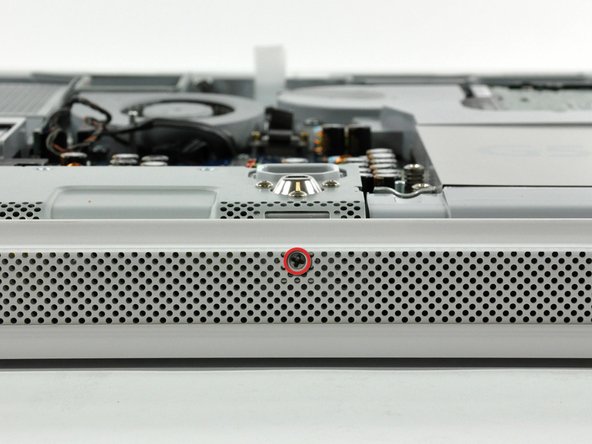
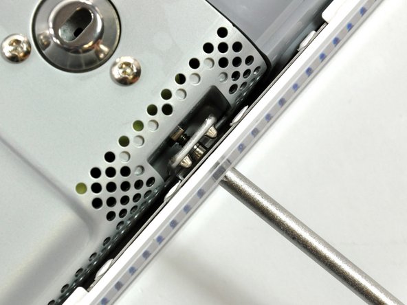
    • Rotate the center Phillips screw on the bottom of the iMac clockwise until the rear panel clamp contacts the edge of the case.

  5. iMac G5 20" Model A1076 Logic Board Replacement: step 5, image 1 of 3 iMac G5 20" Model A1076 Logic Board Replacement: step 5, image 2 of 3 iMac G5 20" Model A1076 Logic Board Replacement: step 5, image 3 of 3
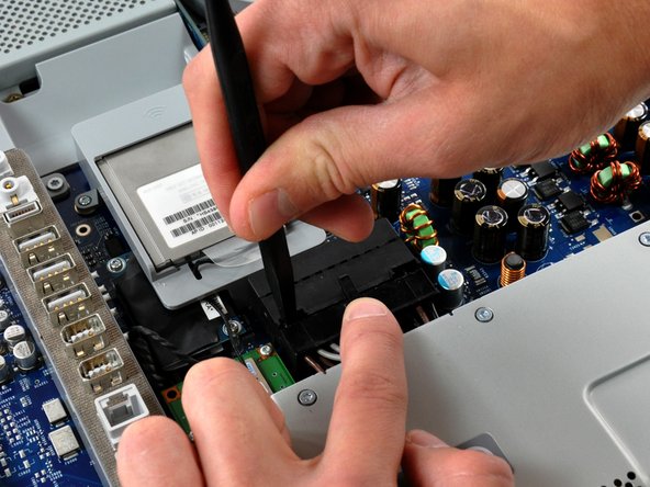
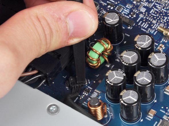
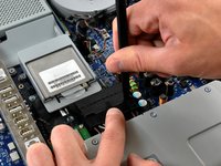
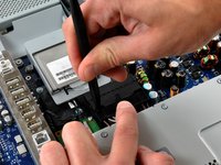
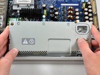
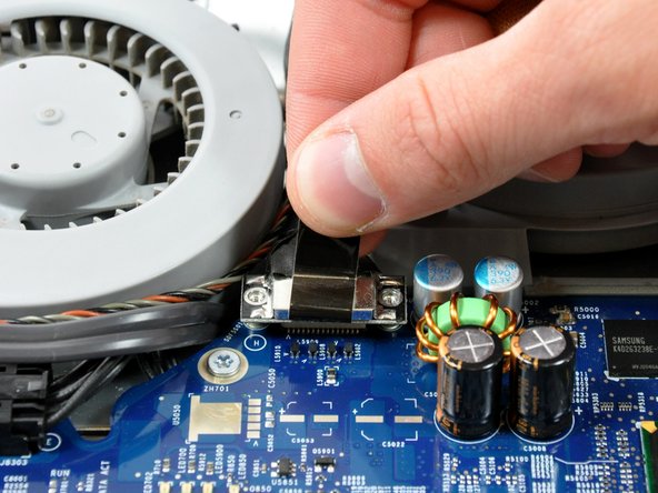
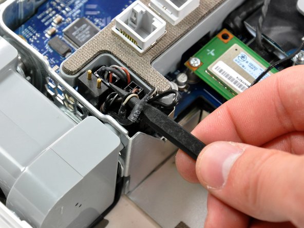
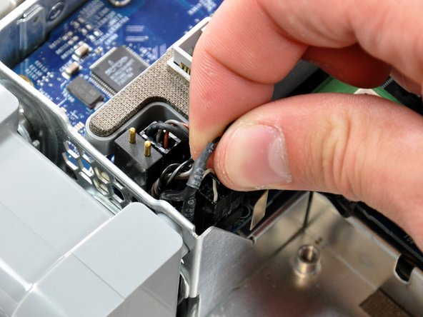
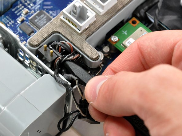
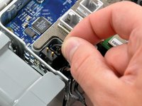
    • While depressing the connector lock, use a heavy duty spudger to pry the power supply connector away from its socket on the logic board.

    • It will be necessary to work from alternate sides until the connector is free.

    • Your power supply may have an ambient light sensor cable attached from the power supply to the logic board. If so, carefully use a spudger to push out the cable towards you using the sides of the cable alternatively to help you slide it out.

  6. iMac G5 20" Model A1076 Logic Board Replacement: step 6, image 1 of 3 iMac G5 20" Model A1076 Logic Board Replacement: step 6, image 2 of 3 iMac G5 20" Model A1076 Logic Board Replacement: step 6, image 3 of 3
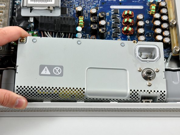
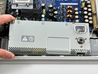
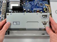
    • Lift the power supply slightly from its left edge, then grab each side and rotate the power supply toward yourself.

    • The power supply requires a large amount of force to remove. You may need to bend the edge of the front case toward yourself for enough clearance to remove the power supply.

    • There are several capacitors mounted to the logic board in close proximity to the power supply. Try not to disturb them, as they are delicate and may break off the board.

  7. iMac G5 20" Model A1076 Logic Board Replacement: step 7, image 1 of 2 iMac G5 20" Model A1076 Logic Board Replacement: step 7, image 2 of 2
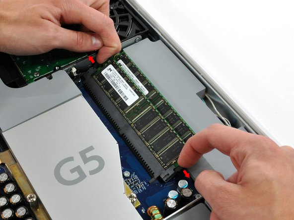
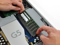
    • Rotate each of the two RAM retaining arms away from the RAM chip.

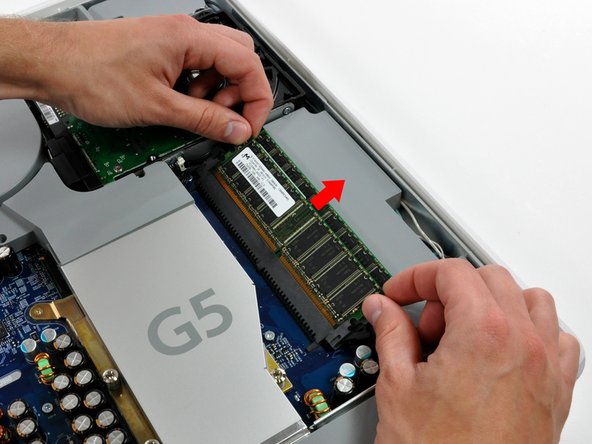
    • Pull the RAM chip straight away from its socket.

    • Repeat this process for the other RAM chip.

    • Be sure the RAM arms are rotated fully outward before installing new RAM chips.

  8. iMac G5 20" Model A1076 Logic Board Replacement: step 8, image 1 of 1
    • Remove the following two screws:

    • One 11 mm T10 Torx.

    • One 10.6 mm T8 Torx.

  9. iMac G5 20" Model A1076 Logic Board Replacement: step 9, image 1 of 1
    • Lift the fan duct out of the chassis.

  10. iMac G5 20" Model A1076 Logic Board Replacement: step 10, image 1 of 1
    • Remove the two 7.3 mm Phillips screws securing the display data cable to the logic board.

  11. iMac G5 20" Model A1076 Logic Board Replacement: step 11, image 1 of 1
    • Pull the display cable up off the logic board by its black pull tab.

  12. iMac G5 20" Model A1076 Logic Board Replacement: step 12, image 1 of 2 iMac G5 20" Model A1076 Logic Board Replacement: step 12, image 2 of 2
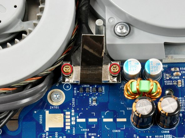
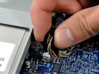
    • Disconnect both the left and right fan connectors by pulling them straight up off the logic board.

    • If you bend the pins on the logic board, use the fan connector as a guide to bend them straight.

  13. iMac G5 20" Model A1076 Logic Board Replacement: step 13, image 1 of 1
    • Disconnect the SATA data cable by pulling its connector straight up off the logic board.

  14. iMac G5 20" Model A1076 Logic Board Replacement: step 14, image 1 of 1
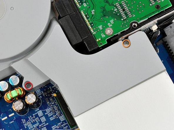
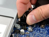
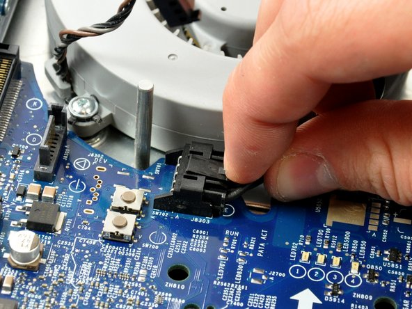
    • Disconnect the SATA power cable by depressing the lock mechanism and pulling the connector straight away from its socket (parallel to the face of the logic board).

  15. iMac G5 20" Model A1076 Logic Board Replacement: step 15, image 1 of 1
    • Remove the four 7 mm Phillips screws securing the optical drive to the midplane.

  16. iMac G5 20" Model A1076 Logic Board Replacement: step 16, image 1 of 2 iMac G5 20" Model A1076 Logic Board Replacement: step 16, image 2 of 2
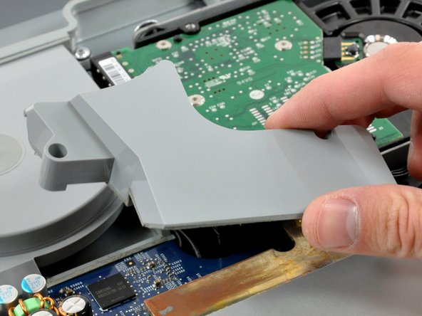
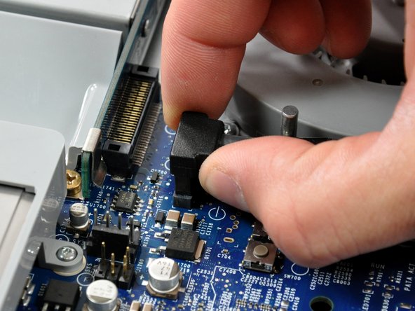
    • Pull the optical drive up by its white pull tab to disconnect it from the logic board.

    • Lift the free end of the optical drive just enough to clear the fan cover. Lifting the free end of the optical drive too far may break the plastic positioning pins off the front bezel.

    • Lift the free end of the optical drive slightly, then pull it away from the edge of the rear case to clear the two plastic positioning pins.

    • Lift the optical drive out of your iMac.

    • When reinstalling your optical drive it may be necessary to set the bezel attached to the open end of the drive on the plastic positioning pins molded into the front bezel of the iMac and pull the connector side of the drive toward the edge of the rear case, bending it outward slightly, to properly seat the connector.

  17. iMac G5 20" Model A1076 Logic Board Replacement: step 17, image 1 of 2 iMac G5 20" Model A1076 Logic Board Replacement: step 17, image 2 of 2
    • Use the tip of a spudger to lift the speaker cable slightly.

    • Disconnect the speaker cable by pulling its connector straight up from the logic board.

  18. iMac G5 20" Model A1076 Logic Board Replacement: step 18, image 1 of 2 iMac G5 20" Model A1076 Logic Board Replacement: step 18, image 2 of 2
    • Use the tip of a spudger to slightly lift the lower fan cable and microphone cable.

    • Disconnect the fan and microphone cables by pulling their connectors straight up from the logic board.

  19. iMac G5 20" Model A1076 Logic Board Replacement: step 19, image 1 of 1
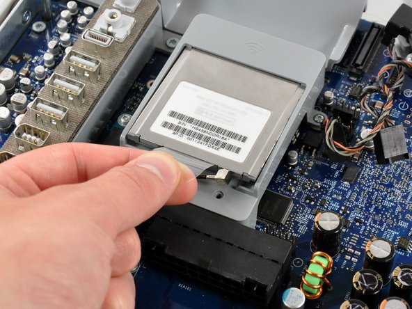
    • Lift the AirPort card slightly by its plastic tab and pull it straight away from its socket.

  20. iMac G5 20" Model A1076 Logic Board Replacement: step 20, image 1 of 1
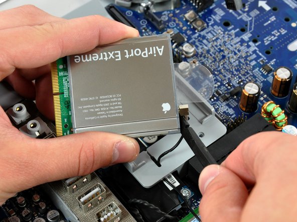
    • Insert the flat end of a spudger between the body of the AirPort card and its antenna connector.

    • Push the spudger away from the AirPort card to disconnect the AirPort antenna.

    • When reassembling your iMac, be sure to insert the AirPort card the way it was before disassembly.

  21. iMac G5 20" Model A1076 Logic Board Replacement: step 21, image 1 of 1
    • Use a spudger to push the AirPort antenna through the gap in the AirPort bracket.

    • Pull the AirPort antenna out from underneath the AirPort bracket.

  22. iMac G5 20" Model A1076 Logic Board Replacement: step 22, image 1 of 1
    • Remove the two 5.5 mm T6 Torx screws securing the Bluetooth board to the logic board.

  23. iMac G5 20" Model A1076 Logic Board Replacement: step 23, image 1 of 2 iMac G5 20" Model A1076 Logic Board Replacement: step 23, image 2 of 2
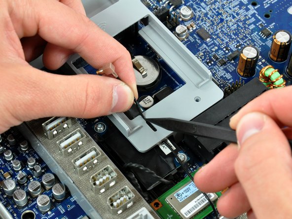
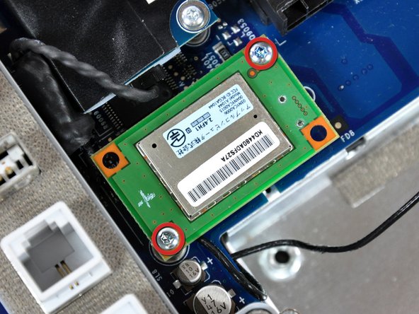
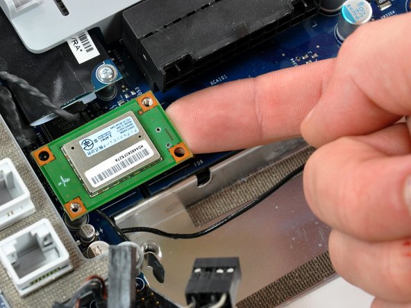
    • Use your finger to lift the Bluetooth board from the right edge up off its socket on the logic board.

    • Be sure to only apply upward force, as any sideways force may cause the connector to shear off the Bluetooth board.

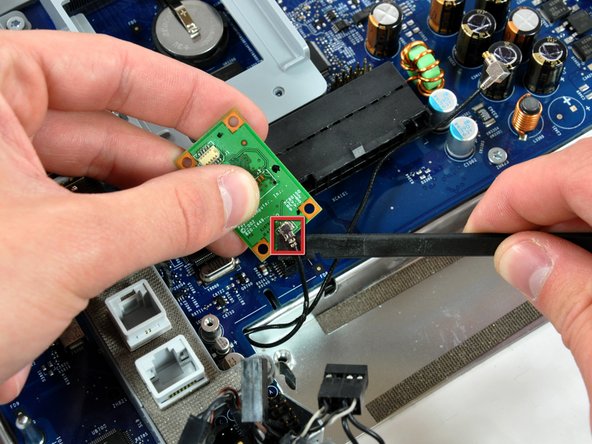
    • Use a spudger to pry the antenna connector off the Bluetooth board.

  24. iMac G5 20" Model A1076 Logic Board Replacement: step 24, image 1 of 1
    • Disconnect the hard drive thermal sensor cable from the hard drive thermal sensor board.

  25. iMac G5 20" Model A1076 Logic Board Replacement: step 25, image 1 of 1
    • Remove the following three screws:

    • One shouldered 12.4 mm Phillips.

    • Two 7 mm T10 Torx.

    • The two Torx screws may be Phillips in some units.

  26. iMac G5 20" Model A1076 Logic Board Replacement: step 26, image 1 of 2 iMac G5 20" Model A1076 Logic Board Replacement: step 26, image 2 of 2
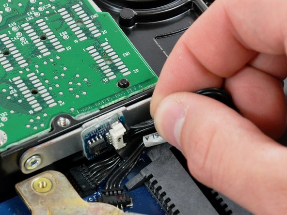
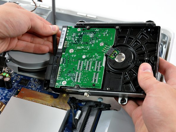
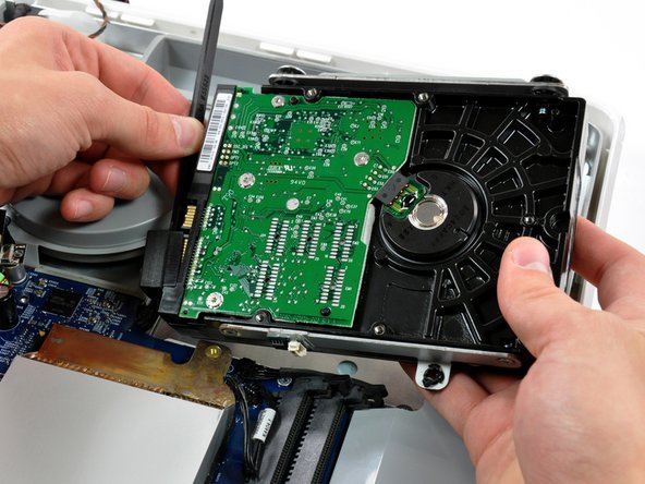
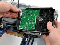
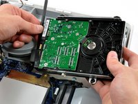
    • Insert the flat end of a spudger into the gap between the SATA data connector and the hard drive.

    • Twist the spudger to separate the SATA data connector from the hard drive, then disconnect it from the hard drive.

    • Repeat this process for the SATA power connector.

  27. iMac G5 20" Model A1076 Logic Board Replacement: step 27, image 1 of 1
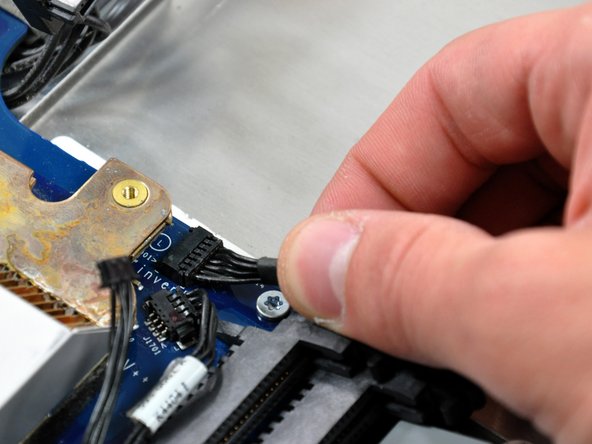
    • Disconnect the black inverter cable from its socket on the logic board by pulling the cable straight away from its socket toward the side of the iMac.

  28. iMac G5 20" Model A1076 Logic Board Replacement: step 28, image 1 of 1
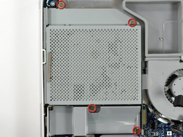
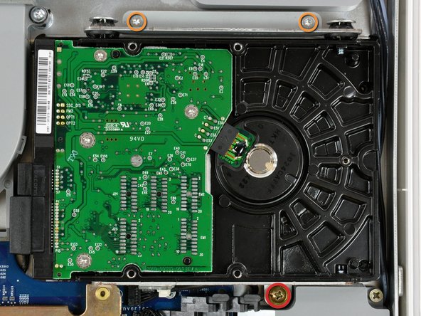
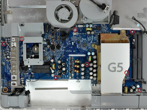
    • Remove the following 9 screws securing the logic board to the midplane:

    • Eight 7 mm T10 Torx.

    • One 26 mm Phillips.

  29. iMac G5 20" Model A1076 Logic Board Replacement: step 29, image 1 of 1
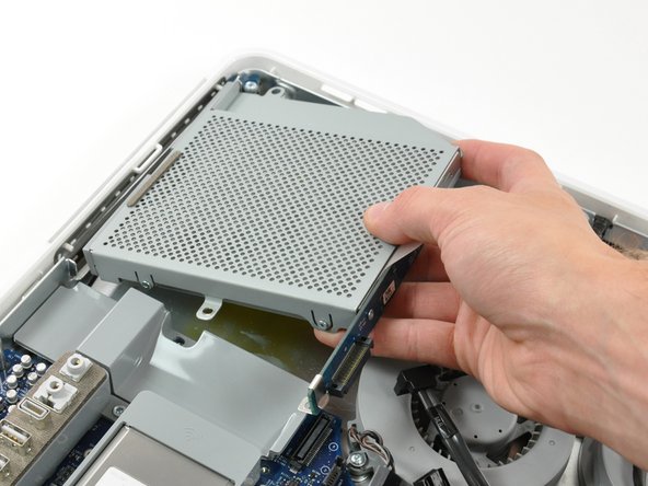
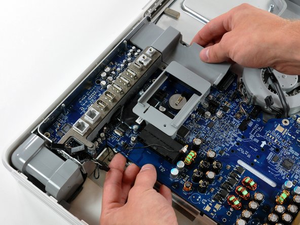
    • Gently lift the logic board from its left side to clear the two pins mounted to the midplane.

  30. iMac G5 20" Model A1076 Logic Board Replacement: step 30, image 1 of 2 iMac G5 20" Model A1076 Logic Board Replacement: step 30, image 2 of 2
    • Lift the logic board out of the midplane. Careful, there is a light guide on the lower left that can tear if you are not careful. This guides the light to the power-on light at the front of the iMac.

    • When reinstalling your logic board, be sure to clean and apply a new layer of thermal paste to the U3 chip (highlighted in red) located on the underside of your logic board as well as its heat sink attached to the midplane.

    • We have a thermal paste guide that makes applying thermal paste a snap.

Conclusion

To reassemble your device, follow these instructions in reverse order.

System

Member since: 09/24/09

2,562 Guides authored

0 Comments

Add Comment

View Statistics:

Past 24 Hours: 0

Past 7 Days: 0

Past 30 Days: 0

All Time: 1