/

iMac Intel 20" EMC 2133 and 2210 Power Supply Replacement

What you need

Video Overview

  1. iMac Intel 20" EMC 2133 and 2210 Power Supply Replacement, iMac Intel 20" EMC 2133 and 2210 Power Supply Replacement: step 1, image 1 of 1
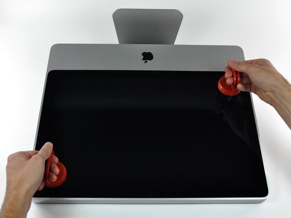
    • Loosen the single Phillips screw in the center of the access door.

    • This screw is captive in the access door.

    • Remove the access door from your iMac.

  2. iMac Intel 20" EMC 2133 and 2210 Power Supply Replacement: step 2, image 1 of 2 iMac Intel 20" EMC 2133 and 2210 Power Supply Replacement: step 2, image 2 of 2
    • The glass panel is fixed onto the front bezel with fourteen magnets around its perimeter.

    • Stick two suction cups to opposing corners of the glass panel.

    • To attach the we sell, first position the suction cup with the movable handle parallel to the face of the glass panel. While lightly holding the suction cup against the glass, raise the movable handle until it is parallel with the other handle.

    • If your suction cups refuse to stick, try cleaning both the glass panel and the suction cup with a mild solvent such as Windex.

  3. iMac Intel 20" EMC 2133 and 2210 Power Supply Replacement: step 3, image 1 of 1
    • Gently pull the glass panel straight up off the iMac.

    • The glass panel has several positioning pins around its perimeter. To avoid shearing these pins off the glass panel, be sure to only pull straight up during removal.

    • Be meticulous about cleaning the LCD and the inside face of the glass panel before reinstallation, as any fingerprints or dust trapped inside will be annoyingly visible when the display is on. Placing the glass flat, inside face down, on a fresh aluminum-foil surface is a good way to keep it clean.

  4. iMac Intel 20" EMC 2133 and 2210 Power Supply Replacement: step 4, image 1 of 1
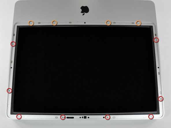
    • Remove the following 12 screws securing the front bezel to the rear case:

    • Eight 13 mm T8 Torx.

    • Four 25 mm T8 Torx.

  5. iMac Intel 20" EMC 2133 and 2210 Power Supply Replacement: step 5, image 1 of 1
    • Disconnect the microphone cable connector, removing tape as necessary.

    • For the front bezel to sit properly, be sure to tuck the microphone cable and connector into the void next to the camera board.

  6. iMac Intel 20" EMC 2133 and 2210 Power Supply Replacement: step 6, image 1 of 2 iMac Intel 20" EMC 2133 and 2210 Power Supply Replacement: step 6, image 2 of 2
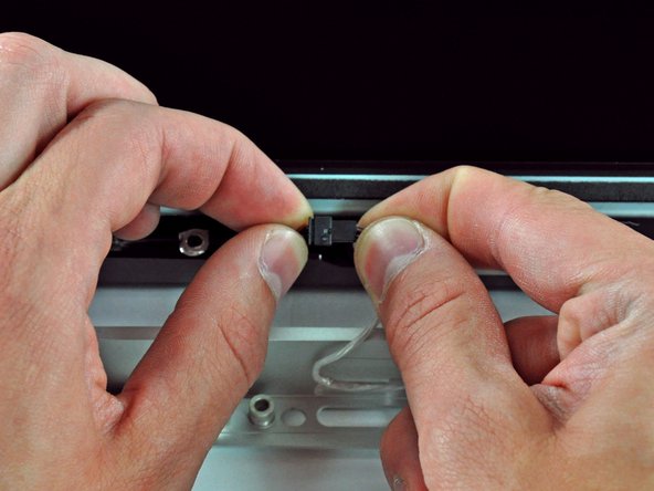
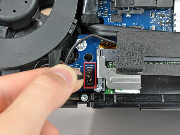
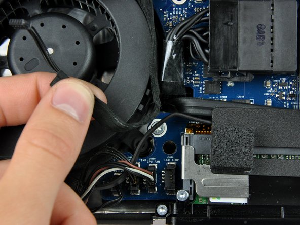
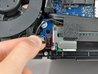
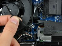
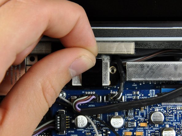
    • Pull the LCD temperature sensor connector straight up out of its socket on the logic board.

    • If necessary, de-route the LCD temperature sensor cable from behind the logic board.

    • When you remove the LCD, check the routing of the LCD temperature display cable. On reinstalling the display, be sure this cable does not block one of the bottom screws for the front bezel.

  7. iMac Intel 20" EMC 2133 and 2210 Power Supply Replacement: step 7, image 1 of 1
    • Remove the two 5.3 mm T6 Torx screws securing the data display cable to the logic board.

  8. iMac Intel 20" EMC 2133 and 2210 Power Supply Replacement: step 8, image 1 of 1
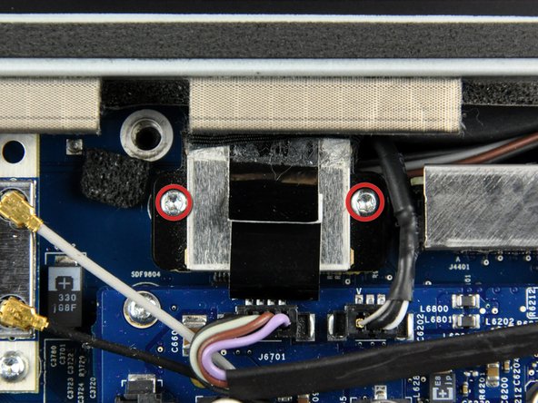
    • Use the attached black tab to pull the data display cable connector away from the logic board.

  9. iMac Intel 20" EMC 2133 and 2210 Power Supply Replacement: step 9, image 1 of 2 iMac Intel 20" EMC 2133 and 2210 Power Supply Replacement: step 9, image 2 of 2
    • Remove the eight 12 mm T8 Torx screws securing the display panel to the rear case.

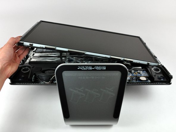
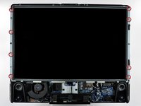
    • Lift the display panel from its left edge and rotate it toward the right edge of the iMac.

  10. iMac Intel 20" EMC 2133 and 2210 Power Supply Replacement: step 10, image 1 of 2 iMac Intel 20" EMC 2133 and 2210 Power Supply Replacement: step 10, image 2 of 2
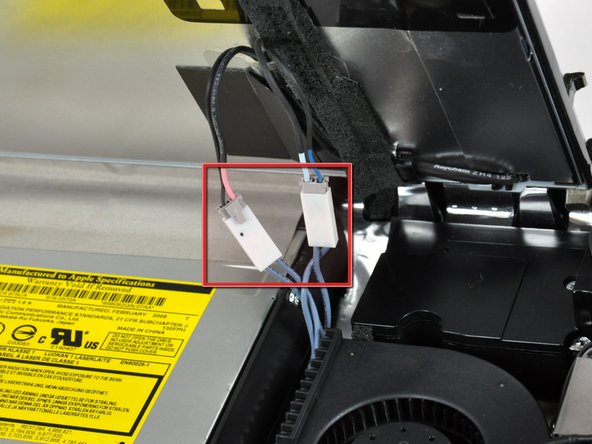
    • With the display panel still lifted, disconnect the four inverter cables.

    • During reinstallation, place the four inverter cable connectors in voids between components attached to the rear panel so the display panel will sit flush.

    • During reassembly, the order of the inverter cables is interchangeable within each socket.

    • If you are replacing a hard drive and have an extra set of hands, it is possible to reach in and remove the drive without disconnecting anything but the LCD temp and display connector in the previous step with the LCD in its propped position.

  11. iMac Intel 20" EMC 2133 and 2210 Power Supply Replacement: step 11, image 1 of 1
    • The next few steps bring your hands close to the exposed face of the power supply. Do not touch the face of the power supply to avoid a high voltage shock from the many large capacitors attached to the board.

    • Remove four T10 Torx screws securing the power supply to the rear case.

    • Two fine-thread 7 mm T10 Torx

    • Two coarse-thread 7 mm T10 Torx

  12. iMac Intel 20" EMC 2133 and 2210 Power Supply Replacement: step 12, image 1 of 2 iMac Intel 20" EMC 2133 and 2210 Power Supply Replacement: step 12, image 2 of 2
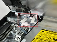
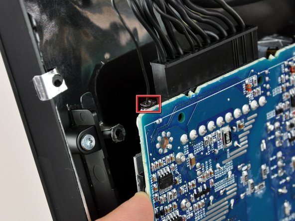
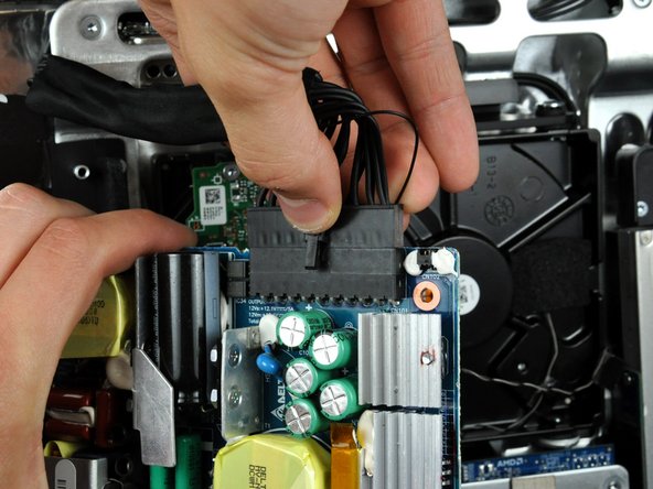
    • Rotate the top edge of the power supply slightly away from the rear case.

    • The single-wire connector near the upper left corner of the power supply is small and held very tightly in its socket, making it inherently difficult to remove. Be sure to pull only on the connector during removal, as pulling the cable will surely cause it to break.

    • The single wire shown in the first photo is for the power supply temperature sensor. If you have power supply temperature issues after installation, check this connection first.

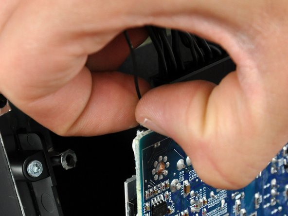
    • Grab the connector between the nails on your thumb and index fingers and pull it toward the top of your iMac, disconnecting it from the power supply.

  13. iMac Intel 20" EMC 2133 and 2210 Power Supply Replacement: step 13, image 1 of 1
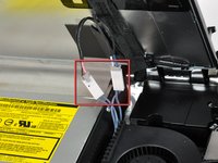
    • Rotate your power supply toward the optical drive.

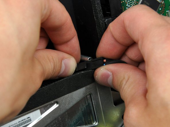
    • Disconnect the DC power cable by simultaneously depressing its lock mechanism and pulling the connector away from its socket.

    • It may help to wiggle the connector while pulling it away from its socket.

  14. iMac Intel 20" EMC 2133 and 2210 Power Supply Replacement: step 14, image 1 of 1
    • Disconnect the AC-in cable by simultaneously squeezing the cable lock and pulling the connector away from its socket.

Conclusion

To reassemble your device, follow these instructions in reverse order.

System

Member since: 09/24/09

2,562 Guides authored

0 Comments

Add Comment

View Statistics:

Past 24 Hours: 0

Past 7 Days: 0

Past 30 Days: 0

All Time: 9