
Introduction
This guide will show you how to replace your iMac's logic board.
What you need
-
-
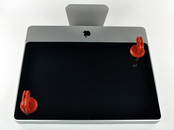
Lay your iMac front side down on a table with the lower edge facing yourself.
-
Loosen the single Phillips screw in the center of the access door.
-
Remove the access door from your iMac.
-
-
-
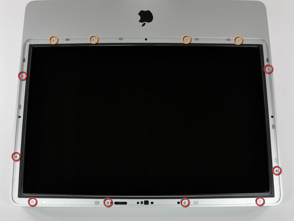
Remove the following 12 screws securing the front bezel to the rear case:
-
Eight 13 mm T8 Torx.
-
Four 25 mm T8 Torx.
-
-
-
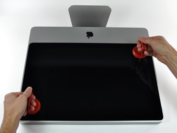
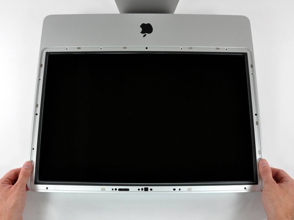
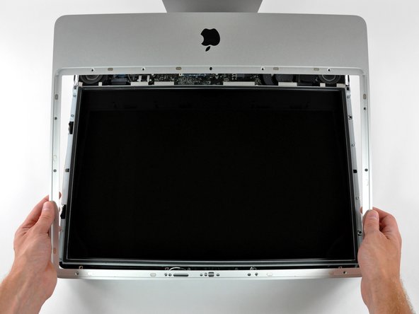
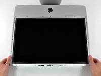
Gently lift the front bezel from its top edge off the rear case.
-
Once the top edge of the front bezel has cleared the rear case, rotate the front bezel toward the stand and lift it off the rear case.
-
Rotate the front bezel away from the rest of the device and lay it above the top edge of the iMac.
-
-
-
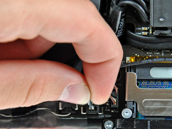
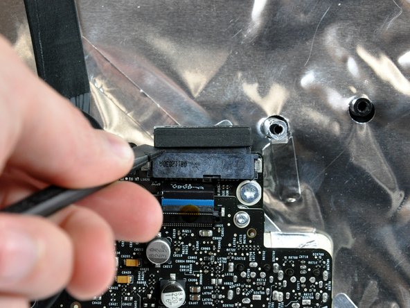
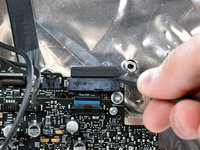
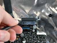
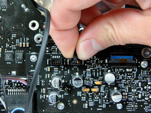
Pull the LCD temperature sensor connector straight up off its socket on the logic board.
-
(located at the top of the logic board on the 24")
-
-
-
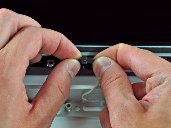
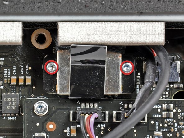
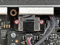
Remove the two T6 Torx screws securing the display data cable to the logic board.
-
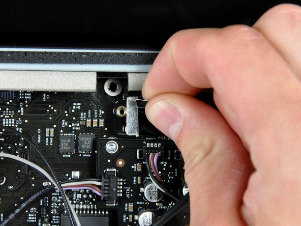
Use the attached black tab to pull the display data cable connector straight away from the logic board.
-
-
-
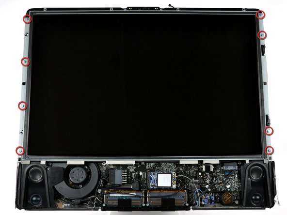
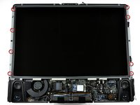
Remove the eight T8 Torx screws securing the display panel to the rear case.
-
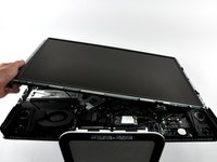
Lift the display panel from its left edge and rotate it toward the right edge of the iMac.
-
-
-
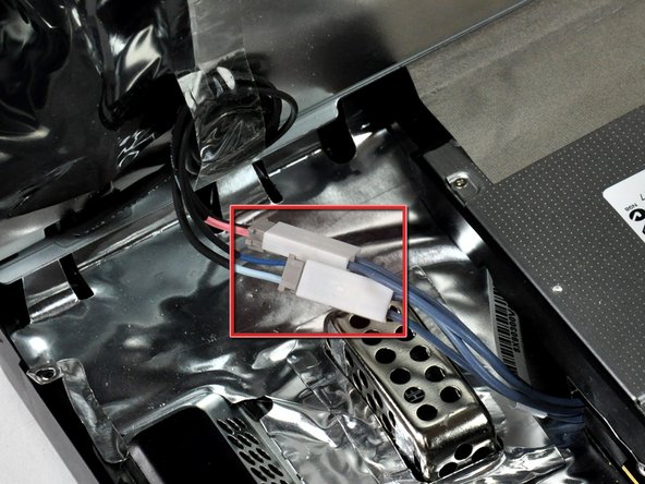
With the display panel still lifted, disconnect the four inverter cables.
-
(combined into one plug in on the 24")
-
-
-
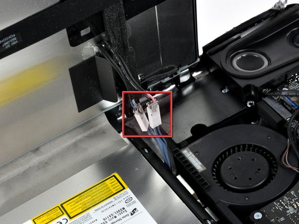
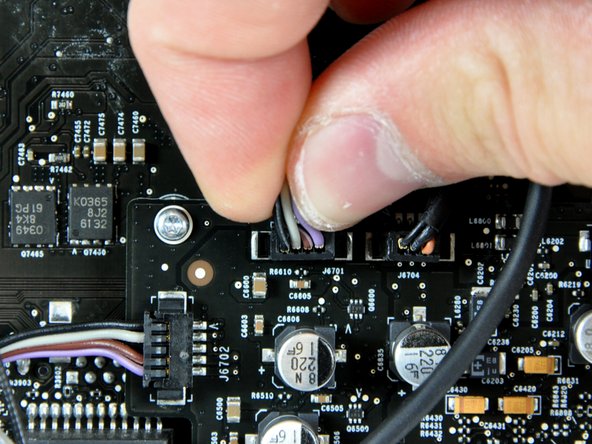
Disconnect the right speaker cable connector from the audio board by pulling it straight up from its socket.
-
-
-
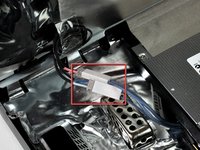
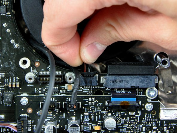
Disconnect the optical drive fan connector from the audio board by pulling it straight away from its socket.
-
-
-
Insert the flat end of a spudger into the gap between the optical drive data cable connector and its socket.
-
Twist the spudger to separate the connector from its socket.
-
-
-
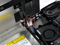
Disconnect the microphone cable connector from the audio board by pulling it straight up from its socket.
-
-
-
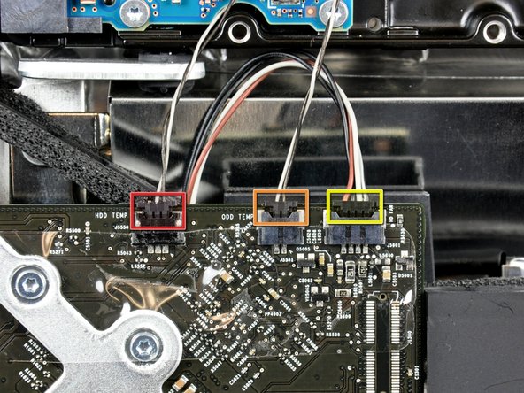
Disconnect the following connectors:
-
Hard drive thermal sensor cable.
-
Optical drive thermal sensor cable.
-
Hard drive fan cable.
-
-
-
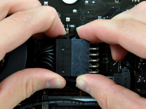
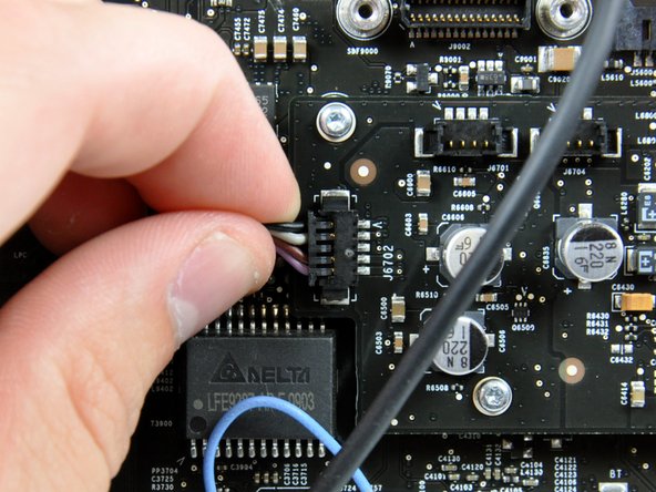
Disconnect the DC-in cable by simultaneously depressing both locking arms and pulling its connector away from the socket on the logic board.
-
-
-
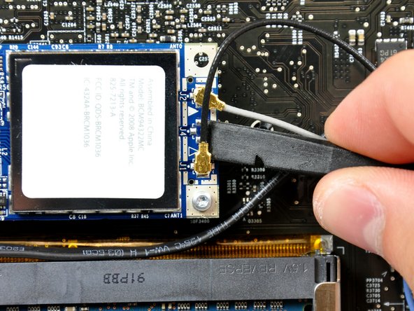
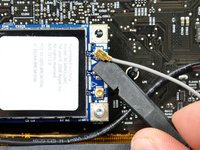
Use the flat end of a spudger to pry both antenna connectors up off the AirPort Extreme card.
-
-
-
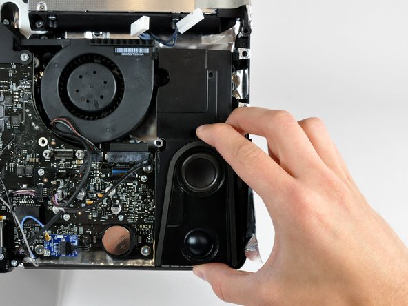
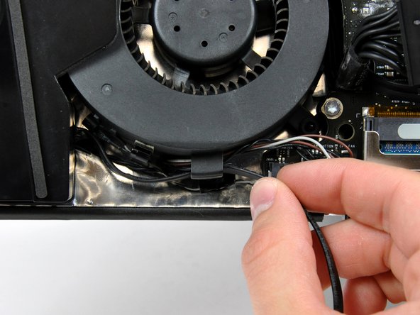
Disconnect the left speaker connector from the audio board by pulling it straight away from its socket.
-
-
-
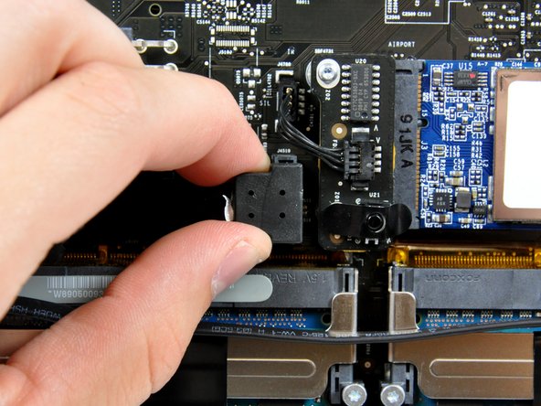
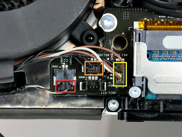
Disconnect the following connectors:
-
Ambient temperature sensor cable.
-
Power button cable.
-
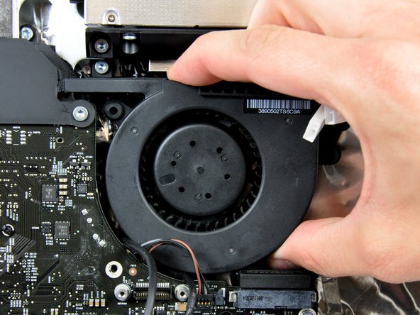
CPU fan cable.
-
-
-
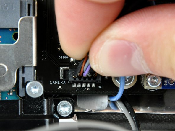
Disconnect the camera cable connector from the logic board by pulling it straight up from its socket.
-
-
-
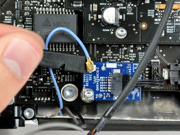
Use the flat end of a spudger to pry the bluetooth antenna connector up off the bluetooth board.
-
-
-
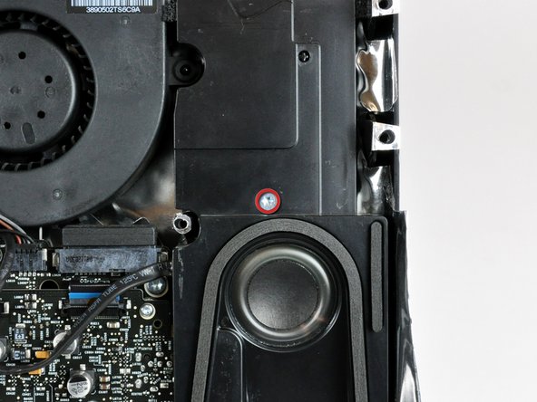
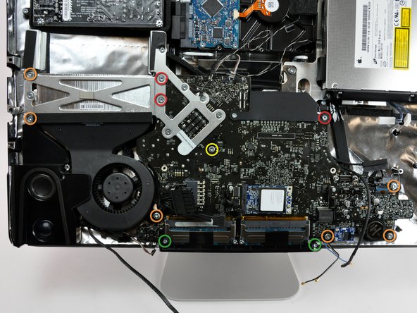
Remove the following screws securing the logic board to the rear case:
-
Three fine-thread T10 Torx.
-
Six coarse-thread T10 Torx.
-
One longer coarse-thread T10 Torx.
-
Two coarse-thread T8 Torx.
-
-
-
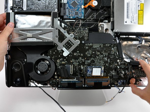
Lift the logic board assembly out of the rear case, minding any cables or I/O ports that may get caught.
-


To reassemble your device, follow these instructions in reverse order.
